Panoramic spine endoscope device

A panoramic, spine technology, applied in the fields of endoscopy, laparoscopy, medical science, etc., can solve the problems of inability to observe the back of the internal fixator, increase the difficulty of operation, and difficult to judge, and achieve 3D stereoscopic observation effect, The effect of reducing surgical trauma and eliminating blind spots in observation

Active Publication Date: 2016-02-03
SUZHOU DIANHE MEDICAL TECH
View PDF6 Cites 12 Cited by
  • Summary
  • Abstract
  • Description
  • Claims
  • Application Information

AI Technical Summary

Problems solved by technology

However, if more complicated spinal surgery such as endoscopic spinal internal fixation is carried out, since spinal internal fixators such as fusion cages, steel plates, and pedicles usually have a large volume or extend out of the working channel for a long time, the existing The endoscopic working channel will appear powerless
[0004] In actual use, because fusion cages, steel plates, pedicles, etc. will block the observation of the endoscope, there will be obvious blind spots in the field of vision, and the operator feels a lot of pressure. Squeeze important tissues such as nerves, which not only increases the difficulty of operation but also brings great risks to endoscopic spinal internal fixation surgery

Method used


Image

  • Panoramic spine endoscope device
  • Panoramic spine endoscope device
  • Panoramic spine endoscope device

Examples


Embodiment 1

[0041] Embodiment 1, taking cooperation with cervical posterior laminoplasty as an example.

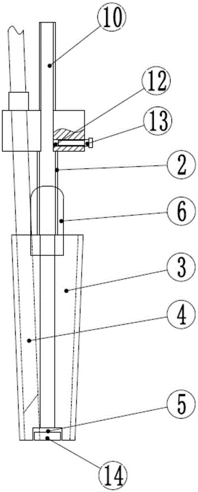
[0042] A small incision was taken in the middle of the back of the cervical spine, and the skin, subcutaneous tissue, and nuchal ligament were incised in sequence. First place the working channel on the surface of the lamina next to the spinous process on one side. Install the endoscope through the left endoscope fixing hole 7 or the right endoscope fixing hole 8, and then adjust the focal length and the direction of view. After the soft tissue is cleaned up, use a burr or lamina rongeur to open a bone groove for decompression along the long axis of the human body.

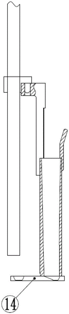
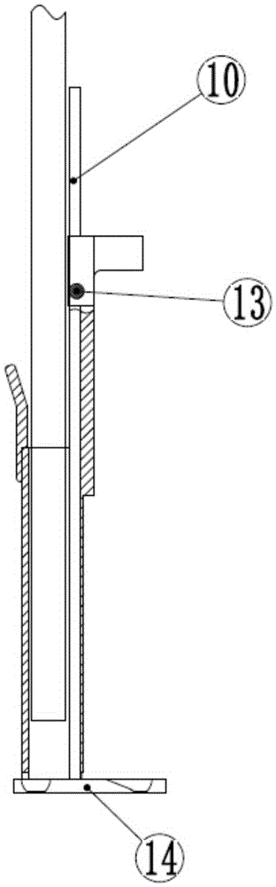
[0043] Then, select a suitable length of micro-titanium plate and bend it, and place it in the steel plate groove 5 of the expansion cylinder 1 . Then, punch a hole in the side block, and fix one end of the steel plate 14. The endoscope 3 is installed in the rear endoscope fixing hole 9 again to adjust the focal length...

Embodiment 2

[0045] Embodiment 2, taking the unilateral intervertebral approach for lumbar instability as an example.

[0046] Take the corresponding part of the body surface of the intervertebral space of the unstable segment and make a small posterior midline incision, and unilaterally incise the lumbar dorsal fascia along the side of the spinous process to insert the present invention. Afterwards, the endoscope 3 is installed in the left endoscope fixing hole 7, and the focal length and the direction of view are adjusted simultaneously. After a small bone window was opened in the lamina, the ligamentum flavum was separated and excised to expose the dural sac and nerve roots.

[0047]According to the actual situation, the nerve root is retracted with the multifunctional sheet 10 to expose the intervertebral disc, the nucleus pulposus tissue is resected, and the upper and lower end plates are scraped off. Moreover, when the first fusion device is inserted, the endoscope 3 is installed in...


PUM


Abstract

The invention relates to a panoramic spine endoscope device. The panoramic spine endoscope device comprises an expansion barrel, and an endoscope supporting column is installed on the expansion barrel. The panoramic spine endoscope device is characterized in that an endoscope and an instrument passing hole are formed in the expansion barrel, a resisting assembly is arranged below the expansion barrel, and a soft tissue reactor piece is arranged above the expansion barrel; meanwhile, a plurality of fixing holes are formed in the tail of the endoscope supporting column, a multifunctional piece assembly is connected to the endoscope supporting column, and an auxiliary fixing assembly is arranged on the endoscope supporting column. Thus, the requirement for switching use of a single-endoscope structure and a double-endoscope structure is met, the left and right side faces of an internal fixator and even the exterior of the expansion barrel can be seen in a time-sharing mode, and dead-zone-free panoramic observation is achieved; observation dead zones can be eliminated, and the 3D observation effect can be achieved.

Description

technical field [0001] The invention relates to an auxiliary instrument for spinal minimally invasive surgery, in particular to a panoramic spinal endoscope device. Background technique [0002] There are many types of endoscopes currently used for minimally invasive spinal surgery, including discoscopy, foraminal microscopy, laparoscopy, and thoracoscopy. In actual operation, they must first establish a working channel when they work. Specifically, it includes a single cylindrical shape (endoscope, suction device, forceps and other instruments pass through a channel), or a multi-hole conical shape (endoscope, suction device, forceps and other instruments pass through the corresponding channel), and the skin, muscle, etc. Wait for the soft tissue to get out of the way. Then, insert the endoscope and use various instruments to complete different technical operations through the lumen of the working channel, such as nucleus pulposus removal and simple decompression. [0003...

Claims


Application Information

Patent Timeline
Patent Type & Authority Applications(China)
IPC IPC(8): A61B1/317A61B17/00A61B1/018A61B17/02
Inventor 张春霖
Owner SUZHOU DIANHE MEDICAL TECH
Why Eureka
Try Eureka