Telescopic device for absorbing collision energy of railway vehicle

A rail vehicle, collision energy absorption technology, applied in the direction of railway vehicle wheel guards/buffers, buffer cars, transportation and packaging, etc., can solve the problems of residual deformation and inability to make full use of the deformation stroke, so as to improve the energy absorption capacity, Protect the safety of vehicles and passengers and realize the effect of automatic control

Active Publication Date: 2016-02-03
CENT SOUTH UNIV
View PDF7 Cites 41 Cited by
  • Summary
  • Abstract
  • Description
  • Claims
  • Application Information

AI Technical Summary

Problems solved by technology

[0005] The energy-absorbing structure of the above-mentioned air-driven retractable automobile collision buffer energy-absorbing device adopts crush deformation. Although the energy-absorbing structure is hidden inside the shell and does not occupy external space before deformation, there will be residual after the energy-absorbing structure is crushed and deformed. Deformation, can not make full use of the deformation stroke

Method used


Image

  • Telescopic device for absorbing collision energy of railway vehicle
  • Telescopic device for absorbing collision energy of railway vehicle
  • Telescopic device for absorbing collision energy of railway vehicle

Examples


Embodiment Construction

[0031] In order to make the purpose, technical solutions and advantages of the embodiments of the present invention more clear, the technical solutions in the embodiments of the present invention will be fully described below in conjunction with the drawings in the embodiments of the present invention. The described embodiments are some, but not all, embodiments of the invention.

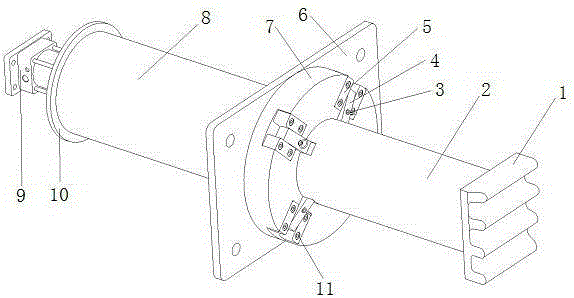
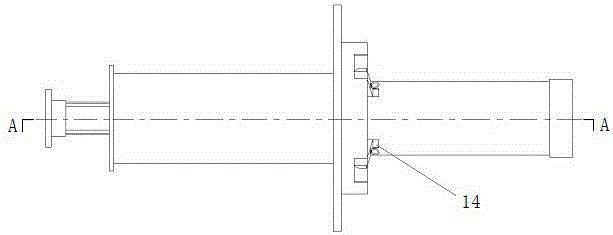
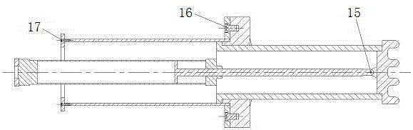
[0032] The utility model relates to a retractable rail vehicle collision energy absorbing device, which is composed of two sets of mechanisms acting independently, which are respectively installed on both sides of the vehicle end. Such as figure 1 and figure 2 As shown, the mechanical structure of the energy-absorbing device consists of anti-climbing teeth 1, energy-absorbing round tube 2, pull ring 3, cutter 4, cutter fixing block 5, mounting seat 6, cutter holder 7, guide cylinder 8, double-acting cylinder 9, rear seat 10, bolt 11, torsion spring 12 and pin 13 form. The energy-absorbing device...


PUM


Abstract

The invention discloses a telescopic device for absorbing collision energy of railway vehicle. The telescopic device comprises two mechanisms which function independently and are respectively mounted on the two sides of a vehicle end part, wherein each mechanism comprises an anti-crawling tooth, a circular energy-absorbing tube, pull rings, cutters, cutter fixing blocks, a mounting base, a cutter base, a guiding cylinder, a double-acting cylinder, a base, bolts, a torsion spring, a dowel, locating grooves, a double-acting electromagnetic valve, a controller and an air storage tank. The telescopic device is characterized in that when the device is in a non-working state, each double-acting cylinder is in a tension state and pulls the corresponding circular energy-absorbing tube to retract inside the corresponding guiding cylinder; each cutter is pressed on the outer wall of the corresponding circular energy-absorbing tube; before trains collide, each double-acting cylinder pushes the corresponding circular energy-absorbing tube to be ejected out under the action of high pressure air; each cutter is pressed on the corresponding locating groove of the corresponding circular energy-absorbing tube under the action of the force of the corresponding spring; when each circular energy-absorbing tube retracts towards the interior of the corresponding guiding cylinder under the action of external force, a cutter cutting type energy absorbing structure absorbs energy; and if the circular energy-absorbing tubes are not hit after stretching out, each circular energy-absorbing tube is separated from the corresponding cutters through pulling the corresponding cutters or jacking up the cutter heads through the corresponding cylinder under the corresponding cutters, and each double-acting cylinder pulls the corresponding circular energy-absorbing tube into the corresponding guiding cylinder.

Description

technical field [0001] The invention belongs to the field of rail vehicle passive safety protection, and in particular relates to an energy absorbing device in vehicle collision. Background technique [0002] With the development of my country's railway transportation and the continuous improvement of train operating speed, more and more attention has been paid to the safety of vehicle operation. Due to the large inertia and high speed of rail vehicles, although emergency braking is performed before encountering obstacles, the Collision accidents still happen from time to time. Once a collision accident occurs, it may cause a tragedy of machine crash. Installing an energy-absorbing structure at the end of the vehicle can make the energy-absorbing structure absorb energy in the event of a collision accident, thereby protecting passengers and vehicles. Safe and popular all over the world. [0003] The invention patent with the publication number CN201989738U is a pneumatically ...

Claims


Application Information

Patent Timeline
Patent Type & Authority Applications(China)
IPC IPC(8): B61F19/04
CPCB61G11/16B61D15/06B61F19/04F16F7/125F16F7/127B61F99/00
Inventor 高广军
Owner CENT SOUTH UNIV
Why Eureka
Try Eureka