Rotary control valve

A technology of control valve and rotary valve, which is applied in the direction of fluid pressure actuators, servo motor components, mechanical equipment, etc., can solve problems such as leakage, valve stem processing valve card, etc., to achieve reduced leakage, excellent pressure holding performance, The effect of easy operation

A technology of control valve and rotary valve, which is applied in the direction of fluid pressure actuators, servo motor components, mechanical equipment, etc., can solve problems such as leakage, valve stem processing valve card, etc., to achieve reduced leakage, excellent pressure holding performance, The effect of easy operation

CN105298962BActive Publication Date: 2017-05-17LIUZHOU LIUGONG HYDRAULIC COMPONENTS +1

Image

  • Rotary control valve
  • Rotary control valve
  • Rotary control valve

Examples


Embodiment Construction

[0020] The specific implementation will be described below in conjunction with the accompanying drawings.

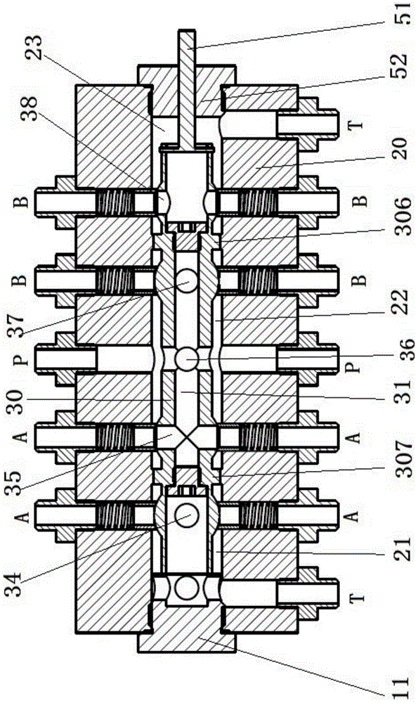
[0021] like figure 1 As shown, in this embodiment, the control valve is used in the steering system, which includes a valve body 20, a valve chamber is arranged in the valve body 20, a valve stem 30 is arranged in the valve chamber, and two ends of the valve chamber are respectively provided with Locate the plug and stem turning mechanism.

[0022] like figure 1 As shown, the valve stem positioning mechanism is a valve cavity plug 11 that is threadedly connected to the left end of the valve cavity. The valve cavity plug 11 is threadedly connected with the valve body to play the role of plug sealing. The end of the valve rod is contacted and connected to play the role of axial positioning, and the end surface of the plug 11 of the valve cavity is provided with a cross groove. .

[0023] The valve stem rotation mechanism includes a second valve cavity plug 52 and a val...


PUM


Abstract

The invention relates to a control valve. By means of the control valve, the deficiencies that an existing control valve is large in leakage amount and low in reliability are overcome. The control valve comprises a valve body and a valve rod. The two ends of the valve rod are provided with a positioning mechanism and a rotating mechanism respectively. Valve rod oil channels are formed in the valve rod. The valve rod is provided with spherical sections. Valve rod oil ports communicated with the valve rod oil channels are formed in the spherical sections. Valve port channels which are perpendicular to the valve rod are formed in the valve body. Sleeves are arranged in the valve port channels. One ends of the sleeves make contact with the spherical sections in a line seal mode, and the other ends of the sleeves are provided with springs. The springs provide elastic force for the sleeves. Spring cavities are communicated with valve body oil channels in the valve body. When the valve rod oil ports and the sleeves are opposite, the valve rod oil channels are communicated with the valve body oil channels through the sleeves. According to the rotary-valve-type control valve, when the valve rod is rotated, the valve rod oil channels are communicated with different oil channels in the valve body through the cooperation between the valve rod oil ports and the sleeves, and the trend of oil ways is controlled. The spherical sections are in line-contact connection with the sleeves in a cone sealing mode, good sealing line-contact can be maintained, the control valve cannot be stuck, and the rotary-valve-type control valve has the advantages of being small in leakage amount and high in reliability.

Description

technical field [0001] The present invention relates to a hydraulic control component, more particularly, to a rotary valve type control valve. Background technique [0002] Among the existing hydraulic control valves, they can be roughly divided into two types, one is the slide valve type, this type of valve includes a valve body, and a valve stem is arranged in the valve cavity of the valve body, the valve stem is cylindrical, and there is a valve stem on it. There are multiple cylindrical shoulders, the shoulders are sealed with the inner wall of the valve cavity, and the valve stem moves axially to block or connect the passages between different oil ports on the valve body. The other type is a rotary valve control valve. This type of valve includes a valve body. A valve stem is installed in the valve cavity of the valve body. There is an oil passage in the stem, and at least one of the outlet and the inlet of the oil passage is set on the side surface of the valve stem....

Claims


Application Information

Patent Timeline
17 May 2017
Publication
CN105298962B
IPC
F15B13/02
Inventors
初长祥; 周永飞