Braking power generation mechanism based on cooperation of balls

A technology of brake power generation and brake mechanism, which is applied in the direction of brake parts, brake types, axial brakes, etc., can solve the waste of heat energy consumption, insufficient effectiveness, and the inability of the motor braking torque to meet the braking force requirements of the whole vehicle, etc. problem, to achieve the effect of increasing the energy saving effect

CN105299097AInactive Publication Date: 2016-02-03FUZHOU MAILIAO AUTOMATION EQUIP CO LTD
11 Cites 8 Cited by

Patent Information

Authority / Receiving Office
CN · China
Current Assignee / Owner
Publication Date
2016-02-03
Estimated Expiration
Not applicable · inactive patent

Smart Images

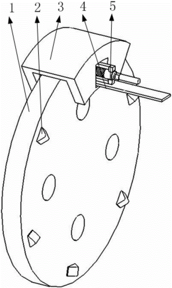
  • Figure 1
    Figure 1
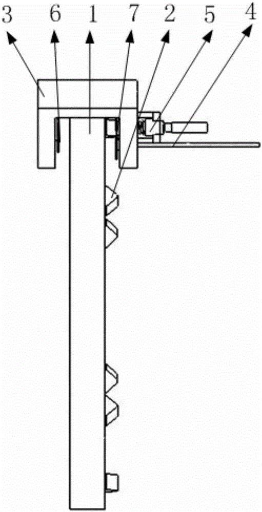
  • Figure 2
    Figure 2
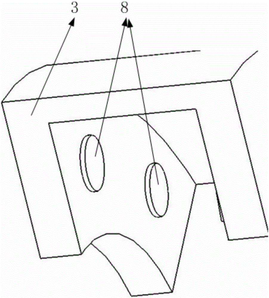
  • Figure 3
    Figure 3
Patent Text Reader

Abstract

The invention belongs to the field of automobile braking energy recycling and particularly relates to a braking power generation mechanism based on the cooperation of balls. The braking power generation mechanism comprises a brake disc, brake disc protrusions, a brake mechanism support, a mechanical braking energy converting mechanism, brake block supports, hydraulic columns, a lead screw, a ball revolute pair, a gear and a power generator, wherein the brake block supports are installed on the brake mechanism support. When the brake disc rotates in the initial stage of braking, brake blocks get close to the brake disc gradually, an ejector block is in contact fit with the protrusions firstly, the ejector block conducts reciprocating rectilinear movement in the direction of a cylindrical guide rail, the ball revolute pair is driven to rotate in a reciprocating mode through cooperation, and accordingly the power generator is driven to generate powder; in the later stage of braking, the brake blocks start to make contact with the brake disc and generate large friction force, and strong braking is conducted on automobile wheels. According to the braking power generation mechanism, the braking energy is converted into reciprocating movement through the cooperation of the ejector block and the protrusions, so that the ball revolute pair is driven to drive the power generator to generate power, the braking energy can be utilized effectively, and the energy saving effect of an automobile is improved.
Need to check novelty before this filing date? Find Prior Art

Description

Technical field

[0001] The invention belongs to the field of automobile braking energy recovery, in particular to a braking power generation mechanism based on ball cooperation. Background technique

[0002] Since the beginning of the 21st century, energy and the environment have had an increasing impact on human life and social development. Energy-saving and emission-reduction technologies for transportation tools are becoming more and more prominent, energy recovery technology for vehicles has been given full attention, and braking energy recovery systems are widely used in electric vehicles and hybrid vehicles.

[0003] At present, the basic principle of braking energy recovery for vehicles with braking energy recovery system is: during the braking process, the motor is used to generate electricity, and at the same time, the electric energy is stored in the power battery to realize the recovery and utilization of braking energy. At this stage, the effectiveness of the br...

Examples

Embodiment Construction

[0034] Such as figure 1 , 2 , 9, 17, and 18, it includes a brake disc, a brake disc protrusion, a brake mechanism support, a first support plate, a mechanical conversion mechanism for braking energy, a first brake pad bracket, a second brake pad bracket, a first Brake hydraulic column, second brake hydraulic column, universal joint, screw, screw support, gear, ball turning pair, gearbox, generator fixed structure, generator, gearbox transmission gear, gearbox transmission shaft, bearings, Among them such as figure 1 As shown, the brake disc protrusions are evenly installed on one side of the brake disc along the circumferential direction, and the brake mechanism is supported and installed on the axle. Supported in the U-shaped groove; such as figure 2 , 3 , 4, 5, and 6, the first brake pad bracket is installed on the inner surface of the brake mechanism support side through two parallel first brake hydraulic cylinders, and the two second brake pad brackets are installed s...