Reduction transmission device with damping gears, and functions of oil gathering and lubrication, and air-pressure balance

A technology of air pressure balance and reducer, applied in the direction of gear lubrication/cooling, components with teeth, belt/chain/gear, etc. It can improve the cooling, avoid the leakage of lubricating oil, and improve the lubrication and cooling effect.

Inactive Publication Date: 2016-02-03
QIJIANG BENLI GEAR CO LTD
View PDF6 Cites 2 Cited by
  • Summary
  • Abstract
  • Description
  • Claims
  • Application Information

AI Technical Summary

Problems solved by technology

[0005] In view of this, the object of the present invention is to provide a reduction transmission with damping gear, oil collection lubrication and air pressure balance function, to solve the gear lubrication and cooling effect of gears in the reducer in the prior art using splash lubrication Poor technical problems; and solve the problem that the gears of the reducer in the prior art do not have a shock-absorbing structure, and there is an impact collision between the gears when the gears mesh, which makes the noise larger and the teeth are prone to breakage when the gears mesh; and solves the existing problems The technical problem of lubricating oil leakage due to the increase of internal air pressure of the parking garage reducer in the technology

Method used


Image

  • Reduction transmission device with damping gears, and functions of oil gathering and lubrication, and air-pressure balance
  • Reduction transmission device with damping gears, and functions of oil gathering and lubrication, and air-pressure balance
  • Reduction transmission device with damping gears, and functions of oil gathering and lubrication, and air-pressure balance

Examples


Embodiment Construction

[0023] The present invention will be further described below in conjunction with the accompanying drawings and embodiments.

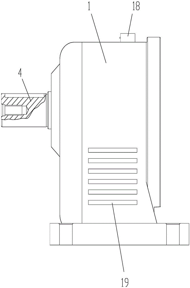
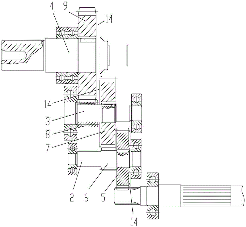
[0024] As shown in the figure, the deceleration transmission with damping gear, oil collection lubrication and air pressure balance function in this embodiment includes a reducer housing 1 and a cylindrical gear transmission mechanism arranged in the reducer housing, and the cylindrical gear transmission mechanism includes The input shaft 2, the intermediate shaft 3 and the output shaft 4 arranged on the reducer housing through bearings, the first gear 5 and the second gear 6 with a diameter smaller than the first gear are arranged on the input shaft, and the intermediate shaft is provided with There is a third gear 7 and a fourth gear 8 with a diameter smaller than that of the third gear. The output shaft is provided with a fifth gear 9. The spline teeth at the end of the rotor shaft mesh with the first gear, and the second gear meshing with the third ...


PUM


Abstract

The invention discloses a reduction transmission device with damping gears, and functions of oil gathering and lubrication, and air-pressure balance. The reduction transmission device comprises a reducer housing, a cylindrical gear transmission mechanism and an oil gathering device, wherein each gear of the cylindrical gear transmission mechanism comprises an inner ring body, an outer ring body and damping blocks; the oil gathering device comprises an annular tube body, partition plates, an oil inlet hole and an oil outlet hole; and an automatic exhaust valve is arranged on the top of the reducer housing. According to the reduction transmission device disclosed by the invention, the gears are stressed by an impact load respectively while being engaged, the damping blocks generate elastic deformations and realize gear damping, noise during the gear engagement can be reduced, and the problem of tooth breakage is avoided; moreover, during working of the reduction transmission device, lubricating oil in an oil storage cavity of the oil gathering device rotates with the gears, so that a part of the lubricating oil can be brought to gear engagement areas to lubricate the gears, and the lubricating and cooling effects of the gears can be improved; and furthermore, when an air pressure in the reducer housing is greater than a sealing air pressure of the automatic exhaust valve, the automatic exhaust valve is opened, and the technical problem of leakage of the lubricating oil due to the rising of the air pressure can be avoided.

Description

technical field [0001] The invention relates to a speed reduction device, in particular to a speed reducer. Background technique [0002] The reducer generally uses lubricating oil to lubricate and cool the gears. Too much lubricating oil in the reducer housing will easily lead to lubricating oil leakage, and too little will easily lead to poor lubrication effect. Therefore, the adding position of lubricating oil in the reducer is generally in the gear One-third to one-half of the lower half, and the gear meshing part is the teeth near the middle of the gear, and the lubricating oil level in the reducer housing is lower than the meshing teeth, so the gear lubrication is the The lubricating oil that is thrown to a high place when the gear rotates, that is, the gear lubrication of the existing reducer adopts the mode of splash lubrication, and the gear lubrication effect is relatively poor. [0003] Moreover, the gears of the reducer in the prior art do not have a shock-absor...

Claims


Application Information

Patent Timeline
Patent Type & Authority Applications(China)
IPC IPC(8): F16H57/028F16H57/04F16H57/027
CPCF16H57/028F16H57/0416F16H57/042F16H2700/00
Inventor 吴思伟刘永平贺良中官志远
Owner QIJIANG BENLI GEAR CO LTD
Why Eureka
Try Eureka