A Method for Measurement of Insertion Loss of Acoustic Overlay Based on Multi-channel Space-Time Inverse Filtering Technology

A technology of acoustic covering and insertion loss, which is applied in the direction of material analysis using acoustic wave emission technology, which can solve the problems of limited measurement ability of low-frequency acoustic performance parameters, measurement signal reverberation interference, and inability to completely absorb sound waves. Requirements for size and test space, elimination of influences, and the effect of facilitating separation

Active Publication Date: 2018-01-12
ZHEJIANG UNIV
View PDF5 Cites 0 Cited by
  • Summary
  • Abstract
  • Description
  • Claims
  • Application Information

AI Technical Summary

Problems solved by technology

The measurement of large samples in the free field has limited ability to measure low-frequency acoustic performance parameters. As the frequency decreases, since the sound-absorbing materials around the measurement environment cannot completely absorb sound waves, the reflection of low-frequency sound waves at the boundary cannot be ignored, and the measurement signal is affected by reverberation. severe interference
At the same time, since the width of the main lobe of the beam will gradually increase with the decrease of the frequency, that is, the resolution of the main lobe will gradually decrease, and the size of the sample to be tested is limited. When the width of the main lobe is larger than the size of the sample to be tested, it will affect the test results. large error

Method used


Image

  • A Method for Measurement of Insertion Loss of Acoustic Overlay Based on Multi-channel Space-Time Inverse Filtering Technology
  • A Method for Measurement of Insertion Loss of Acoustic Overlay Based on Multi-channel Space-Time Inverse Filtering Technology
  • A Method for Measurement of Insertion Loss of Acoustic Overlay Based on Multi-channel Space-Time Inverse Filtering Technology

Examples


Embodiment Construction

[0023] The present invention will be further described below in conjunction with the accompanying drawings.

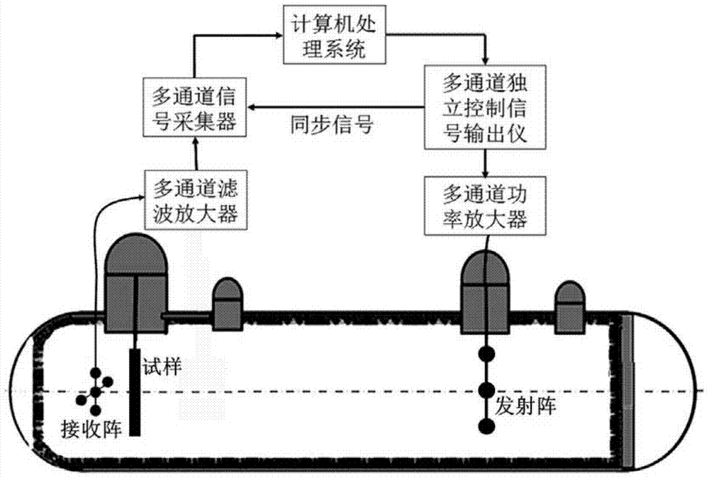
[0024] refer to Figure 1 ~ Figure 4 , a method for measuring insertion loss of acoustic overlays based on multi-channel space-time inverse filtering technology, for the measurement of large-sample insertion loss of acoustic overlays in limited spaces. The technical scheme of the whole measurement method is as follows:

[0025] 1) Generate a multi-channel space-time inverse filter transmission signal;

[0026] In the case of no sample, each transducer of the transducer array transmits the initial signal sequentially, and the hydrophone receives the signal sequentially. The frequency domain of the transmitted signal can be expressed as s(f), where f represents the signal frequency, and the received signal represents for x n (f), wherein n=1, 2,..., N represents the transducer number, and N represents the number of transducers;

[0027] According to the formula

[0...


PUM

PropertyMeasurementUnit
lengthaaaaaaaaaa
densityaaaaaaaaaa

Abstract

Provided is an acoustic coating layer insertion loss measurement method based on a multi-channel space-time inverse filtering technology. The method comprises the following steps that 1, a multi-channel space-time inverse filtering emission signal is generated; 2, a direct signal is collected on the condition that a test sample does not exist; 3, a transmission signal is collected on the condition that the test sample exists; 4, an insertion loss measured value is calculated. According to the acoustic coating layer insertion loss measurement method based on the multi-channel space-time inverse filtering technology, a channel impulse response function containing information of a circuit channel and an underwater acoustic channel is obtained through constant interval emission of an emission array transducer and sequential receiving of a hydrophone, and the purpose of receiving a space acoustic energy focus and a time domain impulse waveform focus of the hydrophone is achieved through the simple and effective multi-channel space-time inverse filtering technology, so that the purposes of multi-path signal separation and reverberation suppression in acoustic coating layer insertion loss measurement are achieved, the space resolution of measurement parameters is improved, and the method is particularly suitable for acoustic performance tests of low-mid frequency materials. Meanwhile, it is verified that the method is effective in acoustic coating layer insertion loss measurement.

Description

technical field [0001] The invention relates to a method for measuring the large-sample insertion loss of an underwater acoustic covering layer. Underwater acoustic cladding is a widely used and crucial underwater component in underwater acoustic engineering. In order to evaluate the insertion loss performance of acoustic cladding samples, the insertion loss measurement of large samples under laboratory conditions is the main method. Background technique [0002] Acoustic covering refers to the special functional acoustic material and structure laid on underwater components, and is an important means for underwater components to achieve acoustic stealth. With the rapid development of viscoelastic materials and the in-depth research on acoustic stealth technology, the acoustic covering layer products are relatively complete, and can be divided into anechoic tiles, sound insulation tiles, vibration suppression tiles, decoupling tiles, and array tiles according to their differe...

Claims


Application Information

Patent Timeline
Patent Type & Authority Patents(China)
IPC IPC(8): G01N29/14
Inventor 李建龙李素旋肖甫
Owner ZHEJIANG UNIV
Why Eureka
Try Eureka