
Maneuvering object frequency modulation stepping retrosynthesis aperture imaging method

A technology of inverse synthetic aperture and FM stepping, which is applied in the direction of radio wave reflection/re-radiation, using re-radiation, measurement devices, etc., which can solve the problems of inability to image, range-Doppler imaging distortion, and low signal quality. Noise ratio and the coherent accumulation of target maneuvering energy can achieve the effect of eliminating errors and improving imaging capabilities

Active Publication Date: 2016-02-03
中机众联(北京)能源科技有限公司
View PDF3 Cites 21 Cited by
  • Summary
  • Abstract
  • Description
  • Claims
  • Application Information

AI Technical Summary

Problems solved by technology

[0007] The technical problems to be solved in the present invention include: 1) under the FM stepping radar system, range migration effect and Doppler migration effect will occur in the echo signal of the maneuvering target, causing the target energy to cross multiple range units and Doppler migration effects. Le unit, the range-Doppler imaging will be distorted, and it will also affect the energy accumulation of the target. In the case of low signal-to-noise ratio, there will be insufficient signal energy to make imaging impossible; 2) The traditional coherent accumulation technology scheme cannot It is a good balance between low signal-to-noise ratio and energy coherent accumulation in the case of target maneuvering movement

Method used


Image

  • Maneuvering object frequency modulation stepping retrosynthesis aperture imaging method
  • Maneuvering object frequency modulation stepping retrosynthesis aperture imaging method
  • Maneuvering object frequency modulation stepping retrosynthesis aperture imaging method

Examples


Embodiment Construction

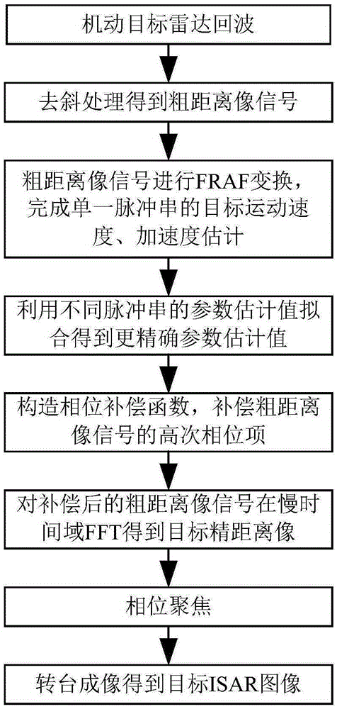
[0029] In order to facilitate the interpretation of the FM stepped radar signal model of the maneuvering target, first derive the following:

[0030] Each cluster of linear frequency modulation (LFM) bursts emitted by stepped frequency modulation radar can be expressed as:

[0031] s(t)=rect[(t-t m ) / T p ]exp[jπμ(t-t m ) 2 ]exp[j2π(f 0 +mΔf)(t-t m )]

[0032] Where t is the full time, t m =mT r +lMT r Is the slow time, m∈[0,M-1], M is the pulse number of a cluster of sub-pulse trains, l∈[0,L-1], L is the number of sub-pulse trains, △f is the frequency step Amount, T p Is the sub-pulse width, T r Is the sub-pulse repetition period, f 0 Is the carrier frequency and μ is the sub-pulse modulation frequency.

[0033] The target echo received by the FM stepping radar is:

[0034] s r (t)=rect[(t-t m -2R / c) / T p ]exp[jπμ(t-t m -2R / c) 2 ]exp[j2π(f 0 +mΔf)(t-t m -2R / c)]

[0035] Perform de-skew processing on the echo signal and the local reference signal, and the difference frequency signal of th...


PUM


Abstract

The invention discloses a maneuvering object frequency modulation stepping retrosynthesis aperture imaging method, belonging to the radar signal processing and imaging technology field. The Maneuvering object frequency modulation stepping retrosynthesis aperture imaging method comprises steps of (1) obtaining a rough distance image after a radar echo is processed by de-slopping, (2) estimating a target movement parameter from a rough distance image signal FRAF transformation spectrogram, (3) utilizing parameter estimate values of various pulse trains to fit an accuracy value, (4) constructing a phase compensation function and compensating a rough distance image signal, (5) obtaining an object fine distance image in a slow time dimension FFT by the compensated rough distance image signal, (6) performing phase focusing on an object fine distance image signal, (7) performing turntable imaging to obtain an ISAR image. The maneuvering object frequency modulation stepping retrosynthesis aperture imaging method can stably estimate the target movement parameter under the low signal to noise ratio, can compensate the distance generated by the object motion and the doppler migration, realizes the accumulation of the phase and parameters, improves the imaging capability of the frequency modulation stepping radar on the maneuvering object under the low signal to noise ratio and has a popularization value.

Description

Technical field [0001] The invention relates to a frequency modulation stepping radar imaging method of a maneuvering target under a low signal-to-noise ratio. The method can be applied to the frequency modulation stepping radar to image a maneuvering target under a low signal-to-noise ratio. Background technique [0002] The FM step signal is an easy-to-implement high-resolution signal. It emits a series of narrow-band FM pulse signals with linear jumps in carrier frequency. After performing two FFT processing on the echo pulse, the high-resolution synthesized distance can be obtained. rate. This signal combines the advantages of stepped frequency and linear frequency modulation pulse signals, and has been widely used, but the existing literature does not have much analysis of frequency modulation stepped radar. [0003] Pulse accumulation imaging is a common method of inverse synthetic aperture (ISAR) radar. Compared with the instantaneous imaging method, the advantage of pulse ...

Claims


Application Information

Patent Timeline
IPC IPC(8): G01S13/90G01S7/41
CPCG01S7/41G01S13/90G01S13/9064
Inventor 罗文茂姜敏敏闫之烨
Owner 中机众联(北京)能源科技有限公司
Learn More