Speckle removing device of laser display

A laser display and speckle technology, applied in optics, optical components, instruments, etc., can solve the problem of inability to eliminate laser display speckle, and achieve the effect of improving display quality

Inactive Publication Date: 2016-02-03
BEIJING UNIV OF TECH
View PDF5 Cites 6 Cited by
  • Summary
  • Abstract
  • Description
  • Claims
  • Application Information

AI Technical Summary

Problems solved by technology

[0005] The technical problem to be solved by the present invention is to solve the problem that the laser display speckle cannot be eliminated under the premise of ensuring the laser power and beam quality in the prior art

Method used


Image

  • Speckle removing device of laser display
  • Speckle removing device of laser display
  • Speckle removing device of laser display

Examples


Embodiment 1

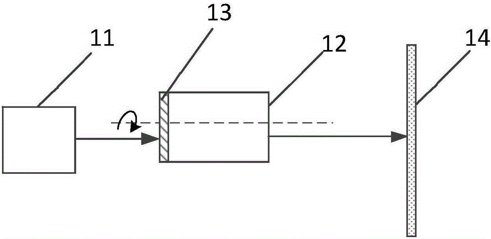
[0032] Such as figure 1 As shown, this embodiment provides a laser display speckle removal device, including: a laser light source 11 and an optical element 12 located in the light emitting direction of the laser light source 11 . In the optical element 12 , the surface facing the laser light source 11 is the laser incident surface 13 . In addition, the device preferably also includes a light screen 14 arranged in the light emitting direction, preferably a white screen. The optical screen 14 is located on the side of the optical element 12 away from the laser light source 11 . Preferably, the laser light source 11 is one or more of red semiconductor lasers, green semiconductor lasers and blue semiconductor lasers. Correspondingly, the wavelengths of each semiconductor laser are 671nm, 532nm and 473nm; the power is 3.5W, 0.32W or 1.3W respectively.

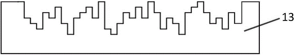
[0033] Such as figure 2 As shown, the laser incident surface 13 also includes several grooves arranged adjacently, and the g...

Embodiment 2

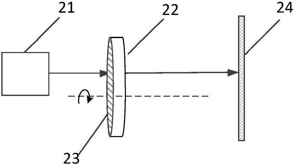
[0036] Such as image 3 As shown, this embodiment is basically the same as Embodiment 1, the difference is that the optical element 22 in this solution is a circular sheet structure, wherein the surface of the circular sheet structure is the laser incident surface 23 .

[0037] When performing speckle removal on the laser beam emitted by the laser light source 21, the optical element 22 is preferably rotated at a high speed on a line perpendicular to the laser incident surface 23 under the action of an external force, and the rotation speed is preferably 10000r / min. Wherein, the axis is parallel to the laser beam, so that the optical element 22 is kept perpendicular to the laser beam and rotates at a high speed. The laser beam whose optical path is changed by the optical element 22 is irradiated on the light screen 24. During the integration period of a human eye, the speckle structure will be continuously superimposed to gradually reduce the contrast of the speckle. When the ...

Embodiment 3

[0040] Such as Figure 4 As shown, this embodiment is basically the same as Embodiment 1, the difference is that the optical element 32 in this solution is a tubular structure with a circular cross-section, wherein the inner surface of the tubular structure is the laser incident surface 33 . The laser light source 31 is located inside the tubular structure, and its light emission direction is perpendicular to the axial direction of the tubular structure, so only a part of the optical element 32 is located in the light emission direction of the laser light source 31 .

[0041]When performing speckle removal on the laser beam emitted by the laser light source 31, the optical element 32 rotates at a high speed around the straight line in the axial direction of the tubular structure under the action of an external force, and the rotation speed is preferably 10000r / min. Wherein, the axis is perpendicular to the laser beam, so that the optical element 32 is kept parallel to the lase...


PUM


Abstract

The invention discloses a speckle removing device of laser display, and relates to the technical field of laser display. The device comprises laser sources and optical components, at least part of the optical components is placed in the light extraction directions of the laser sources, the optical components of transmission type are rotatable, and comprise uneven laser incidence planes respectively, and when the optical components rotate, laser beams emitted by the laser sources continuously pass the laser incidence planes. The rotary optical components are additionally arranged behind the laser sources to change the spatial coherence of laser, enable speckle to overlap continuously in the integration time, reduce the contact of speckles, and weaken the speckles. In addition, the laser sources are constant in the speckle removing process, so that the speckles can be effectively removed on the premise that the laser power and quality of laser beams are ensured, and the display quality is improved.

Description

technical field [0001] The invention relates to the technical field of laser display, in particular to a speckle removal device for laser display. Background technique [0002] Laser display is a new generation of technology after black and white display, color display, and digital display. It is called "the revolution in the history of human vision". Features such as high performance, energy saving and environmental protection will become the mainstream of high-end displays in the future. Laser display technology uses red, green, and blue lasers as light sources, and the red, green, and blue lasers are respectively incident on the corresponding light valve after beam expansion, shimming, and decoherence, and an image modulation signal is added to the light valve. , the modulated three-color laser is combined by the X prism and then incident on the projection objective lens, and finally projected to the screen through the projection objective lens to obtain a laser display ...

Claims


Application Information

Patent Timeline
Patent Type & Authority Applications(China)
IPC IPC(8): G02B27/48
CPCG02B27/48
Inventor 王智勇雷宇鑫尧舜邱运涛贾冠男成健罗校迎
Owner BEIJING UNIV OF TECH
Why Eureka
Try Eureka