Area array sweep frequency measurement device and method

A measuring device and frequency sweeping technology, which is applied in the direction of measuring devices, optical devices, radio wave measuring systems, etc., can solve the problem of low accuracy of laser ranging

Pending Publication Date: 2021-04-20
武汉光目科技有限公司
View PDF0 Cites 6 Cited by
  • Summary
  • Abstract
  • Description
  • Claims
  • Application Information

AI Technical Summary

Problems solved by technology

[0005] In view of the defects of the prior art, the object of the present invention is to provide an area array frequency sweep measurement device and method, aiming at solving the problem of low accuracy of laser ranging due to the unavoidable vibration of the existing area array frequency sweep

Method used


Image

  • Area array sweep frequency measurement device and method
  • Area array sweep frequency measurement device and method
  • Area array sweep frequency measurement device and method

Examples


Embodiment 1

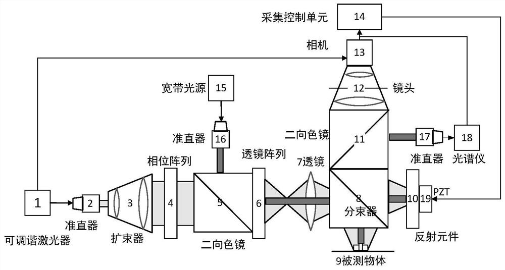
[0067] Such as figure 1 The figure shows an area-array frequency-sweep measurement device for speckle suppression, including a tunable laser 1, a first collimator 2, a beam expander 3, a phase array 4, a first dichroic mirror 5, and a lens array 6 , first lens 7, beam splitter 8, second dichroic mirror 11, lens 12, camera 13, acquisition control unit 14 and reflective element 10, piezoelectric ceramic displacement stage 19, broadband light source 15, second collimator 16. A third collimator 17 and a spectrometer 18;

[0068] A first collimator 2, a beam expander 3, a phase array 4, a first dichroic mirror 5, a lens array 6, a first lens 7, a beam splitter 8, and a reflective element 10 are sequentially arranged in the transmission direction of the laser beam. And piezoelectric ceramic displacement stage 19; The second dichroic mirror 11, lens 12 and camera 13 are arranged successively in the opposite direction of laser beam through beam splitter 8 reflection; The output end o...

Embodiment 2

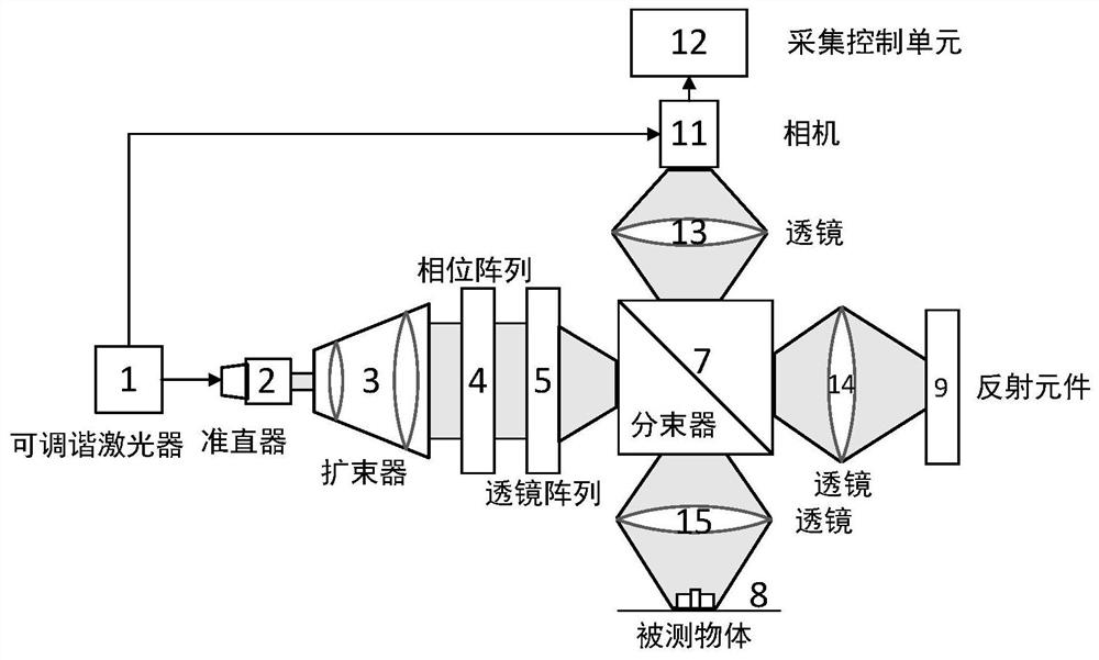
[0082] Such as figure 2 The figure shows an area-array frequency-sweep measurement device for speckle suppression, including a tunable laser 1, a first collimator 2, a beam expander 3, a phase array 4, a first dichroic mirror 5, and a lens array 6 , beam splitter 8, second lens 21, third lens 22, fourth lens 23, second dichroic mirror 11, camera 13, acquisition control unit 14, reflective element 10, piezoelectric ceramic translation stage 19, broadband light source 15. A second collimator 16, a third collimator 17 and a spectrometer 18;

[0083] A first collimator 2, a beam expander 3, a phase array 4, a first dichroic mirror 5, a lens array 6, a beam splitter 8, a third lens 22, and a reflective element 10 are sequentially arranged in the transmission direction of the laser beam. And piezoelectric ceramic displacement stage 19; Laser beam is provided with second lens 21, beam splitter 8, second dichroic mirror 11, fourth lens 23 and camera 13 successively through the direc...


PUM


Abstract

The invention provides an area array sweep frequency measurement device and method, and belongs to the technical field of laser ranging. A beam splitter decomposes a converged light beam into reflected light and transmitted light; during use, a measured object reflects the reflected light to form signal light; a reflecting element is used for reflecting the transmitted light; a second dichroscope is used for decomposing the reflected transmitted light into reference light and wide-spectrum light; a spectrograph is used for acquiring spectral information through the decomposed wide-spectrum light; a camera is used for collecting an interference image formed by interference of the signal light and the reference light; an acquisition control unit can analyze the surface topography of the measured object according to the interference image and the compensation information; vibration information is obtained according to the spectral information and used for controlling a piezoelectric ceramic displacement table to move, and compensation information is obtained. Through superposition of a plurality of independent speckles, the effect of reducing the speckle contrast is achieved; meanwhile, an optical anti-shake function is achieved, and the laser ranging accuracy is improved.

Description

technical field [0001] The invention belongs to the technical field of laser distance measurement, and more specifically relates to an area array frequency sweep measurement device and method. Background technique [0002] In modern industrial production, the precision of parts processing has become more and more the key to high-performance equipment. It is very important to accurately and stably produce the required parts of specific size and shape. Therefore, accurate detection of the produced parts is an important link to ensure high-quality production. In the existing technology, accurate distance measurement in a large field of view often requires point-by-point scanning to obtain the shape of the part, and the measurement speed is also limited by the scanning speed, making it difficult to obtain high measurement speed with high sensitivity. Therefore, it is necessary to develop a large-scale, high-precision, and fast method for measuring the thickness and distance of ...

Claims


Application Information

Patent Timeline
Patent Type & Authority Applications(China)
IPC IPC(8): G01S17/08G01S7/481G01B11/06
Inventor 雷力于龙殷晓君鄢淦威陈哲锋
Owner 武汉光目科技有限公司
Why Eureka
Try Eureka