Internal rotor magnetic suspension spherical surface gyro flywheel

A technology of gyro flywheel and magnetic levitation, which is applied in the direction of gyro effect for speed measurement, gyro/steering sensing equipment, space vehicle guidance device, etc. Improve suspension accuracy and control torque accuracy, improve rotor suspension accuracy, and facilitate the effect of high-precision suspension control

Active Publication Date: 2016-02-03
BEIJING INSTITUTE OF PETROCHEMICAL TECHNOLOGY +1
View PDF6 Cites 30 Cited by
  • Summary
  • Abstract
  • Description
  • Claims
  • Application Information

AI Technical Summary

Problems solved by technology

The deflection torque is superimposed with the deflection control torque output by the Lorentz force magnetic bearing, which reduces the precision of the rotor deflection maneuver, thereby reducing the precision of the output torque of the gyro flywheel

Method used


Image

  • Internal rotor magnetic suspension spherical surface gyro flywheel
  • Internal rotor magnetic suspension spherical surface gyro flywheel
  • Internal rotor magnetic suspension spherical surface gyro flywheel

Examples


specific Embodiment approach

[0018] The preferred embodiment of the inner rotor magnetically suspended spherical gyro flywheel of the present invention is:

[0019]Including the static part and the rotating part, the static part mainly includes: upper gyro room, middle gyro room, lower gyro room, upper sealing ring, lower sealing ring, upper axial spherical magnetic bearing stator, lower axial spherical magnetic bearing stator, upper protection Bearings, lower protective bearings, motor component stators, upper axial displacement sensor components, lower axial displacement sensor components, radial displacement sensor components, radial spherical magnetic bearing stators and Lorentz force magnetic bearing stators; the rotating parts mainly include: The gyro outer turntable assembly, the gyro inner shaft, the sphere center adjustment ring and the gyro rotor lock nut; the upper gyro housing is located at the upper end of the middle gyro housing axially and is fastened to the middle gyro housing by screws, an...

specific Embodiment

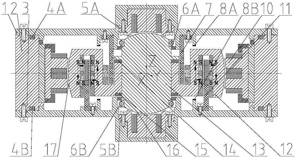
[0031] Such as figure 1 As shown, the present invention is mainly composed of a static part and a rotating part. The static part mainly includes: an upper gyro room 1, a middle gyro room 2, a lower gyro room 3, an upper sealing ring 4A, a lower sealing ring 4B, and an upper axial spherical magnetic bearing 5A stator, lower axial spherical magnetic bearing 5B stator, upper protective bearing 6A, lower protective bearing 6B, motor assembly 7 stator, upper axial displacement sensor assembly 8A, lower axial displacement sensor assembly 8B, radial displacement sensor assembly 9, The radial spherical magnetic bearing 10 stator and the Lorentz force magnetic bearing 11 stator; the rotating part mainly includes: the gyro outer turntable assembly 12, the gyro inner shaft 13, the spherical center adjusting pad ring 14 and the gyro rotor lock nut 15; the upper gyro housing 1 It is located at the axial upper end of the middle gyro room 2 and is fastened to the middle gyro room 2 by screws...


PUM


Abstract

The invention discloses an internal rotor magnetic suspension spherical surface gyro flywheel. The flywheel comprises a stationary part and a rotating part. The stationary part comprises an upper gyro chamber, a middle gyro chamber, a lower gyro chamber, a sealing ring, an axial spherical surface magnetic bearing stator, a protective bearing, a motor assembly stator, an axial displacement sensor assembly, a radial displacement sensor assembly, a radial spherical surface magnetic bearing stator and a Lorentz force magnetic bearing stator. The rotating part comprises a gyro outer rotating disk assembly, a gyro inner rotating shaft, sphere center adjusting backing rings and gyro rotor lock nuts. A spherical surface magnetic bearing is adopted to serve as supporting member, five-degree-of-freedom active suspension of the magnetic suspension gyro flywheel can be achieved, the interference of three times of translation control of a rotor in two times of radial twist control is eliminated, and then the moment precision of the high gyro moment instantly output by the gyro flywheel is increased.

Description

technical field [0001] The invention relates to an inertia actuator that can be used as an attitude control system of an agile mobile satellite platform, in particular to an inner rotor magnetic levitation spherical gyro flywheel. Background technique [0002] Because the momentum exchange system can provide high attitude control accuracy, it is widely used in the attitude control system of spacecraft such as satellites and probes. The flywheel system changes the magnitude of the angular momentum by controlling the rotor speed to generate the required control torque, thereby precisely controlling the attitude of the spacecraft. Increasing the rotational speed can increase the output torque range of the flywheel, but as the rotational speed increases, the life of the flywheel system supported by traditional mechanical bearings will be affected. At the same time, due to the friction of mechanical bearings, the rotor speed cannot be very high. To increase the angular momentum ...

Claims


Application Information

Patent Timeline
Patent Type & Authority Applications(China)
IPC IPC(8): G05D1/08G01C19/00B64G1/28
Inventor 刘强任元樊亚洪缪存孝王卫杰吴波胡灯亮高宪鹏赵航
Owner BEIJING INSTITUTE OF PETROCHEMICAL TECHNOLOGY
Why Eureka
Try Eureka