Control Method of Fixing Mechanism for Dual-purpose Curved Plate Cutting

A technology of a fixing mechanism and a control method, applied in the field of control, can solve the problems of unqualified finished products, the operation table is not suitable for arc plate cutting, etc., and achieves the effect of saving input cost, increasing the scope of application, and widening the scope of application.

Active Publication Date: 2018-11-16
江苏益圆居品制造有限公司
View PDF8 Cites 0 Cited by
  • Summary
  • Abstract
  • Description
  • Claims
  • Application Information

AI Technical Summary

Problems solved by technology

[0006] The purpose of the present invention is to solve the problem that the existing operating desktop is not suitable for cutting arc-shaped plates, and the finished products are likely to be unqualified during cutting; to provide a dual-purpose arc plate suitable for both arc-shaped plate cutting and flat plate cutting. Control Method of Fixing Mechanism for Shaped Plate Cutting

Method used


Image

  • Control Method of Fixing Mechanism for Dual-purpose Curved Plate Cutting
  • Control Method of Fixing Mechanism for Dual-purpose Curved Plate Cutting

Examples


Embodiment 1

[0028] The control method of the fixed mechanism for dual-purpose arc-shaped plate cutting includes:

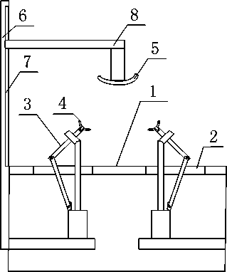
[0029] (1) Place the arc-shaped plate of the distribution cabinet on the operation table between the two angle adjustment parts;

[0030] (2) Start the push cylinder on the angle adjustment part, so that the top of the moving rod is close to the arc plate of the distribution cabinet, and the arc formed between the arc plate of the power distribution cabinet and the operation table body and the top of the two moving rods is consistent with the The arc plates of the power distribution cabinet are consistent; press down the pressing device so that the arc plate of the power distribution cabinet is fixed between the pressing device and the angle adjustment part;

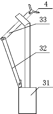
[0031] like figure 1 and figure 2 As shown, the angle adjustment part 3 includes a push cylinder 31, a fixed rod 32 whose bottom end is hinged on the cylinder body of the push cylinder 31, and a moving rod 33 whose b...

Embodiment 2

[0033] The difference between this embodiment and Embodiment 1 is that: the operating table body 1 described in this embodiment is also provided with an installation port 2, and the specific settings are as follows:

[0034] The operating platform is provided with two installation ports 2, and the straight line formed between the two installation ports 2 is in the same direction as the cutting and moving direction of the arc-shaped plate, and an angle adjustment part 3 is installed in each installation port 2; The two angle adjustment parts 3 are arranged symmetrically.

[0035] Example 2

[0036] The difference between this embodiment and Embodiment 1 is that the example in this embodiment optimizes the specific structure of the angle adjustment part 3, such as figure 2 As shown, the specific settings are as follows:

[0037] The top end of the push-pull shaft of the push cylinder 31 is sleeved on the moving rod 33 ; the top end of the moving rod 33 is also provided with a...

Embodiment 4

[0039] The difference between this embodiment and Embodiment 3 is that the specific structure of the pressing device is optimized in this embodiment, and the specific settings are as follows:

[0040] The pressing device includes a vertical bar 6 whose bottom end is fixed on the operation table body 1, a chute 7 arranged on the vertical bar 6, and a connecting rod 8 which is arranged in the chute 7 and is used to move along the chute 7 at one end. , the compression block 5 fixed on the other end of the connecting rod 8.


PUM


Abstract

The present invention discloses a control method of a fixed mechanism for dual-purpose curved plate cutting. The problems that the traditional operating desktop is not applicable to curved plate cutting and finished products cut on the traditional operating desktop are liable to be qualified at cutting are solved. The control method provided by the invention comprises: (1) the curved plate of a power distribution cabinet is disposed on an operating desk body arranged between two angle regulation elements; (2) pushing cylinders on the angle regulation elements are started to make the top of each movable lever close to the curved plate of the power distribution cabinet, the radians formed at the contact position of the curved plate of the power distribution cabinet and the operating desk body and between the tops of the two movable levers are in accordance with the curved plate of the power distribution cabinet; (3) a compacting apparatus is pushed downward to fix the curved plate of the power distribution cabinet between the compacting apparatus and the angle regulation elements; (4) the angle regulation elements include the pushing cylinders, dead levers which have bottom ends hinged to the bodies of the pushing cylinders, and movable levers which have bottom ends hinged at the tops of the dead levers; and (5) the tops of the push-pull shafts of the pushing cylinders are movably connected with the movable levers. According to the invention, the control method of a fixed mechanism for dual-purpose curved plate cutting has the advantages of simple structure and easy operation, etc.

Description

technical field [0001] The invention relates to a control method, in particular to a control method of a dual-purpose fixed mechanism for cutting arc-shaped plates. Background technique [0002] Power distribution cabinets (boxes) are divided into power distribution cabinets (boxes), lighting distribution cabinets (boxes), and metering cabinets (boxes), which are the final equipment of the power distribution system. The power distribution cabinet is a general term for the motor control center. The power distribution cabinet is used in the occasions where the load is relatively scattered and there are few circuits; the motor control center is used in the occasions where the load is concentrated and there are many circuits. They distribute the electric energy of a certain circuit of the upper-level power distribution equipment to the nearest load. This level of equipment shall provide protection, monitoring and control of the load. [0003] In the prior art, in order to bet...

Claims


Application Information

Patent Timeline
Patent Type & Authority Patents(China)
IPC IPC(8): H02B3/00
CPCH02B3/00
Inventor 陈怀之王刚聂海涛张仁友胡国波
Owner 江苏益圆居品制造有限公司
Why Eureka
Try Eureka