Permanent magnet synchronous motor subsection skewed pole positioning rotor

A technology for permanent magnet synchronous motors and positioning rotors, applied to synchronous motors with stationary armatures and rotating magnets, magnetic circuit rotating parts, magnetic circuit shape/style/structure, etc., can solve unfavorable mass production, stator skew Difficulty in embedding wires of slot motors, unfavorable manufacturing, transportation and assembly, etc., to achieve the effect of simple positioning

Inactive Publication Date: 2016-02-03
DONGFENG MOTOR ELECTRIC
View PDF4 Cites 13 Cited by
  • Summary
  • Abstract
  • Description
  • Claims
  • Application Information

AI Technical Summary

Problems solved by technology

Among them, it is difficult to insert wires in the stator inclined motor, which is not conducive to mass production; if the rotor inclined pole motor adopts an integrated magnetic steel structure, the magnetic steel needs to realize circumferential rotation and axial tilt at the same time, which is not conducive to manufacturing, transportation and assembly; Segmented inclined poles, and use the same mold rotor punching, each segment needs an accurate, reliable and simple rotation positioning method to meet the assembly requirements of the motor rotor

Method used


Image

  • Permanent magnet synchronous motor subsection skewed pole positioning rotor
  • Permanent magnet synchronous motor subsection skewed pole positioning rotor
  • Permanent magnet synchronous motor subsection skewed pole positioning rotor

Examples


Embodiment Construction

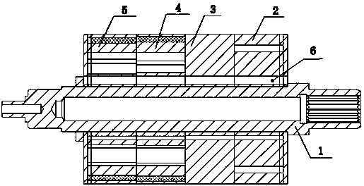
[0026] figure 1 Among them, the present invention includes a rotor shaft (knurled shaft) 1, a rotor core press-fitted on the rotor shaft, and the rotor core is composed of four core segments, namely the first core segment 2, the second core segment 3, The third iron core segment 4, the fourth iron core segment 5, and the positioning through hole 6 after the iron core segments connected in series are rotated.

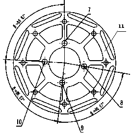
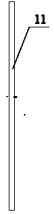
[0027] figure 2 , 3 Among them, punching holes 7, 8, 9, 10 are provided on the rotor punching plate 11, wherein 7 is the positioning base point, and 8, 9, 10 are matching points. The rotor punch 11 is formed by stamping a silicon steel sheet through a die, and the thickness depends on the specification and model, such as 0.35mm, 0.5mm, etc.

[0028] Figure 4 , 5 Among them, the rotor punches 11 are stacked to form hollow rotor segments, and magnetic steel (permanent magnets) 12 are installed in the hollow rotor segment, and the length of each hollow rotor segment ...


PUM


Abstract

The invention relates to a permanent magnet synchronous motor subsection skewed pole positioning rotor, which comprises a rotor shaft and a rotor iron core installed on the rotor shaft, wherein the rotor iron core is composed of at least n iron core sections which are connected in series, each iron core section comprises hollow rotor sections and permanent magnets with at least P pole pairs arranged on the hollow rotor sections, the same magnetic poles of the permanent magnets of two adjacent iron core sections are equidirectionally staggered, and an axially formed skewed pole spiral angle is alpha; the hollow rotor sections are provided with more than one positioning base point located at the same circumference and a plurality of matching points matched with the positioning points, an angle between the positioning base point and the adjacent matching point is beta, and beta=360 degrees/P-alpha/(n-1) or beta=360 degrees/P+alpha/(n-1), wherein the n is greater than or equal to 2, and the P is greater than or equal to 2. The permanent magnet synchronous motor subsection skewed pole positioning rotor can realize rotor iron core section positioning for a rotor subsection skewed pole motor accurately, reliably, simply and conveniently in a mode of the positioning base points and the matching points.

Description

technical field [0001] The invention relates to a segmented inclined pole positioning rotor of a permanent magnet synchronous motor. Background technique [0002] At present, in order to improve the performance of the motor (improve the motor back EMF waveform, reduce the motor cogging torque, reduce the motor noise, improve the motor efficiency, improve the motor control accuracy, etc.), the permanent magnet drive motor mostly adopts two kinds of stator chute or rotor oblique pole. Way. Among them, it is difficult to insert wires in the stator inclined motor, which is not conducive to mass production; if the rotor inclined pole motor adopts an integrated magnetic steel structure, the magnetic steel needs to realize circumferential rotation and axial tilt at the same time, which is not conducive to manufacturing, transportation and assembly; Segmented oblique poles, and the use of the same mold rotor for punching, requires an accurate, reliable, and simple rotational positi...

Claims


Application Information

Patent Timeline
Patent Type & Authority Applications(China)
IPC IPC(8): H02K1/27H02K21/14
Inventor 齐亮
Owner DONGFENG MOTOR ELECTRIC
Why Eureka
Try Eureka