
A fully automatic production line for screw oiling and its process

A production line, fully automatic technology, applied in the direction of coating, the device for coating liquid on the surface, etc., can solve the problems such as the inability to meet the production needs of the enterprise, the low efficiency of screw oiling, the occupation of workers' working hours, etc. The high degree of automation and the effect of improving work efficiency

Active Publication Date: 2018-08-14
RITAI SHANGHAI AUTO STANDARD COMPONENT
View PDF4 Cites 0 Cited by
  • Summary
  • Abstract
  • Description
  • Claims
  • Application Information

AI Technical Summary

Problems solved by technology

[0002] The current screw oiling process is entirely based on the operator manually putting the screw into the oil barrel for oiling work. When taking out the screw, it will often cause waste of oil. At the same time, manual oiling by workers will take up a lot of man-hours for workers, and the efficiency of screw oiling Low, unable to meet the production needs of enterprises

Method used


Image

  • A fully automatic production line for screw oiling and its process
  • A fully automatic production line for screw oiling and its process
  • A fully automatic production line for screw oiling and its process

Examples


Embodiment 1

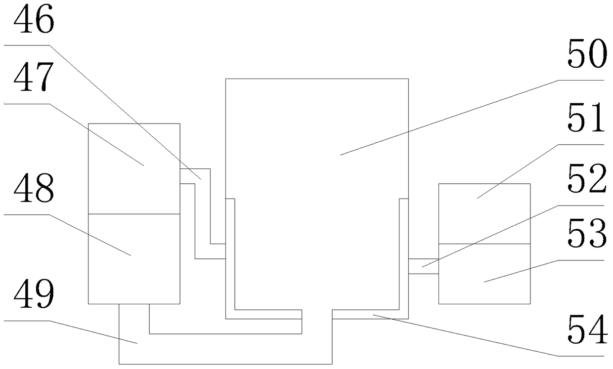
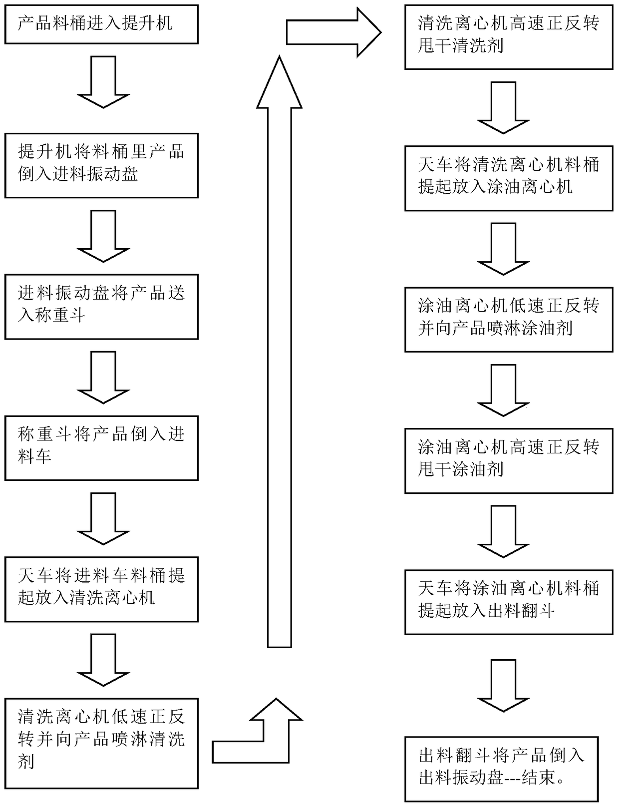
[0039] Such as image 3 As shown, the screw to be oiled is put into the feeding dump 2, and the screw is poured into the feeding vibration plate 3 through the rotation of the tipping bucket support frame 6, and the feeding vibration plate 3 sends the screw into the feeding weighing bucket 8 , the cylinder 7 runs and drives the feed baffle 9 to rise upwards, so that the screw is sent into the material barrel 10, and the manipulator 12 lifts the material barrel 10 and sends it into the cleaning centrifuge 55. The cleaning centrifuge 55 first rotates forward and reverse at a low speed Spray the cleaning agent to the screws in the material barrel 10, then clean the centrifuge 55 forward and reverse at a high speed so that the screws in the material barrel 10 dry the cleaning agent to complete the process of cleaning the centrifuge 55, then hand in hand 12 to lift the material barrel 10 and Put it into the oil-coated centrifuge 56, the oil-coated centrifuge 56 first rotates forward...

Embodiment 2

[0041] Such as Figure 4 As shown, the screw to be oiled is put into the feeding dump 2, and the screw is poured into the feeding vibration plate 3 through the rotation of the tipping bucket support frame 6, and the feeding vibration plate 3 sends the screw into the feeding weighing bucket 8 , the cylinder 7 runs and drives the feed baffle 9 to rise up, so that the screw is sent into the material barrel 10, and the manipulator 12 grabs the material barrel 10 and puts it into the degreasing device 14 for degreasing. After the degreasing is completed, the manipulator 12 grabs the material barrel 10 into the washing device 22, in the washing device 22, three washing tanks are separated by the first baffle plate 17, the second baffle plate 18, the third baffle plate 19 and the side wall of the water washing device 22, and are respectively filled with cold water. , cold water and hot water, wherein a gap overflow 45 is provided between the first baffle plate 17 and the second baffl...


PUM


Abstract

The invention relates to the field of oiling equipment, in particular to a screw oiling full-automatic production assembly line and a technology thereof. The assembly line comprises a base, a feeding device, a manipulator, a cleaning centrifugal machine, an oiling centrifugal machine, a degreasing device, a washing device, a dehydration centrifugal machine, an airing device, an oil immersion tank, a hot air centrifugal machine and a discharging device. The assembly line is characterized in that a frame is arranged above the base, and the feeding device, the cleaning centrifugal machine, the oiling centrifugal machine, the degreasing device, the washing device, the dehydration centrifugal machine, the airing device, the oil immersion tank, the hot air centrifugal machine and the discharging device are sequentially arranged on the base from left to right. Compared with the prior art, the assembly line is convenient to use and high in automation degree, and the procedure needing a dozen of workers to complete only needs one worker now; different oil materials can be added into the oiling tank according to different technologies, and the requirement for screw oiling is met through different technologies.

Description

technical field [0001] The invention relates to the field of oiling equipment, in particular to a screw oiling automatic production line and a process thereof. Background technique [0002] The current screw oiling process is entirely based on the operator manually putting the screw into the oil barrel for oiling work. When taking out the screw, it will often cause waste of oil. At the same time, manual oiling by workers will take up a lot of man-hours for workers, and the efficiency of screw oiling Low, unable to meet the production needs of enterprises. Contents of the invention [0003] In order to overcome the deficiencies of the prior art, the present invention designs a fully automatic production line that can greatly improve the oiling efficiency of screws. [0004] In order to achieve the above purpose, a fully automatic screw oiling production line is designed, including base, feeding device, manipulator, cleaning centrifuge, oiling centrifuge, degreasing device,...

Claims


Application Information

Patent Timeline
Patent Type & Authority Patents(China)
IPC IPC(8): B05C9/14
Inventor 吴金旺
Owner RITAI SHANGHAI AUTO STANDARD COMPONENT
Learn More