cutting device

A technology for cutting and installing grooves, which is applied in metal processing and other directions, can solve the problems of large overall size of the cutting machine, affecting the moving speed, and bulky volume, so as to improve flexibility and convenience, increase moving speed, and avoid direct impact force effect

Active Publication Date: 2018-07-31
广州创速自动化科技有限公司
View PDF6 Cites 5 Cited by
  • Summary
  • Abstract
  • Description
  • Claims
  • Application Information

AI Technical Summary

Problems solved by technology

However, due to its heavy weight, it seriously affects its moving speed; moreover, its volume is relatively large, so it needs to occupy a large space, so that the overall volume of the cutting machine is relatively large

Method used


Image

  • cutting device
  • cutting device
  • cutting device

Examples


Embodiment Construction

[0017] Below, in conjunction with accompanying drawing and specific embodiment, the present invention is described further:

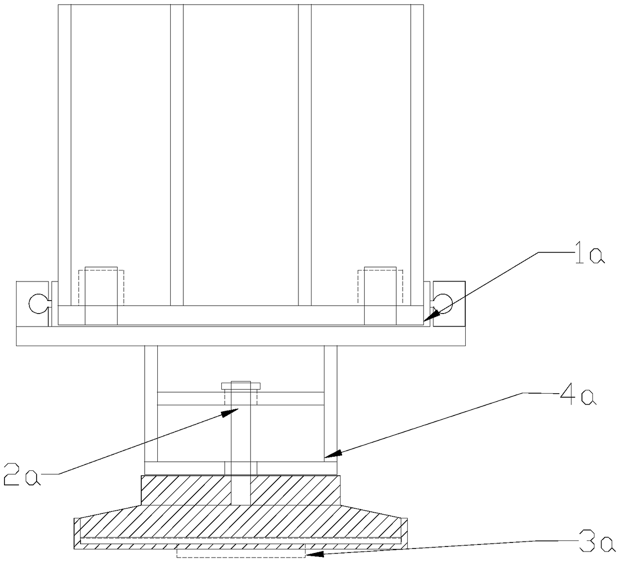
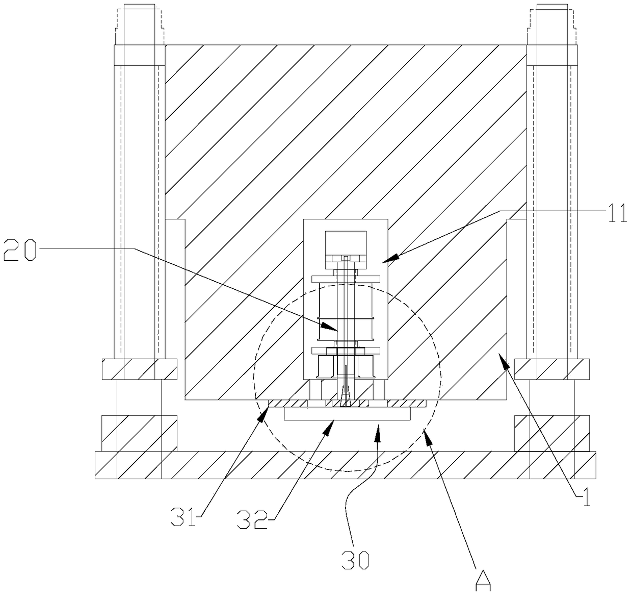
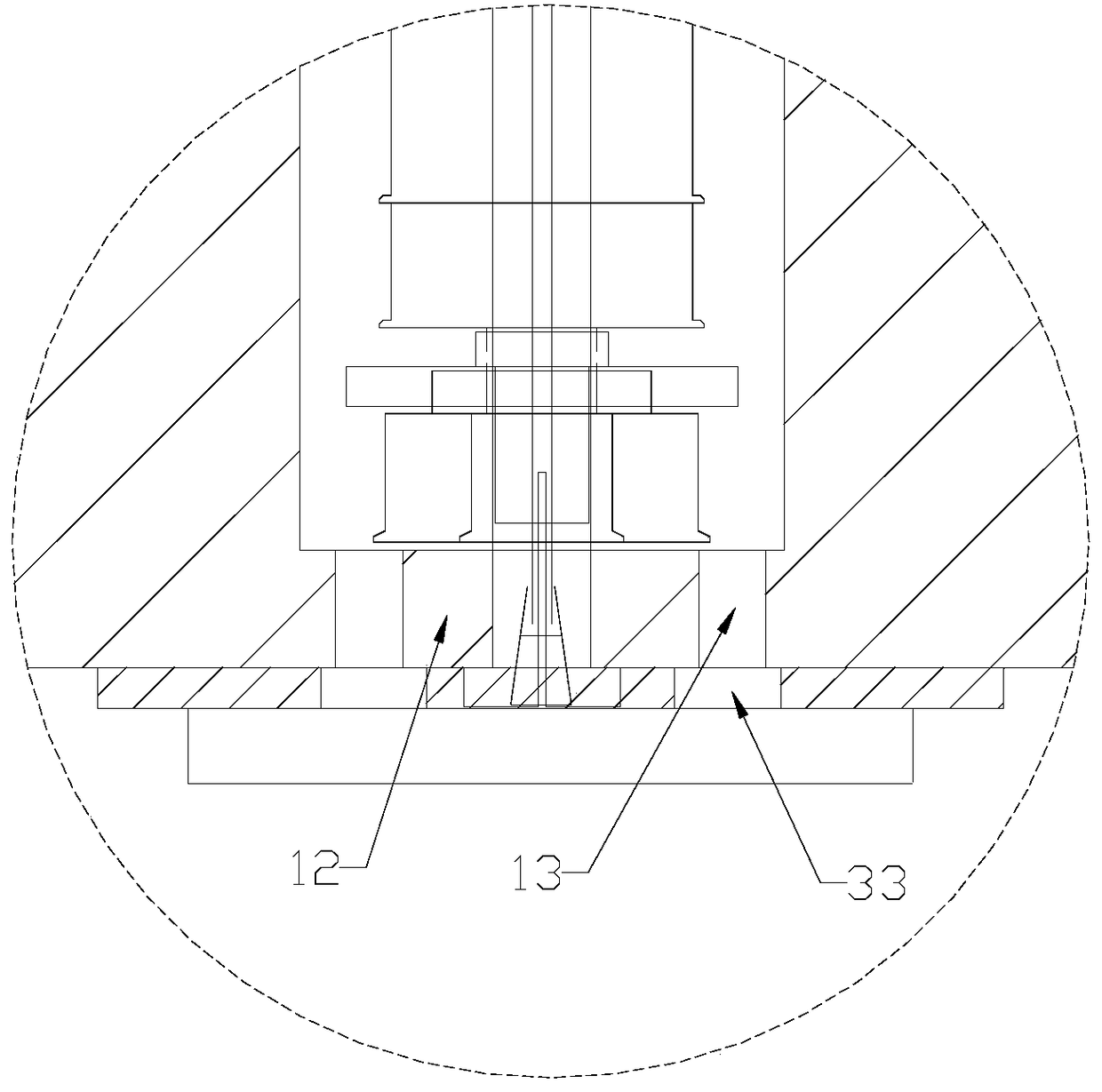
[0018] Such as Figure 2-4 As shown, it is a cutting device of the present invention, which includes an upper platen 1, a knife mold 30, and a knife shaft 20; the upper platen 1 is provided with an installation groove 11 with an opening facing downward and extending along the length direction of the upper platen 1; The knife shaft 20 is located in the installation groove 11 of the upper pressing plate 1; the knife mold 30 is connected to the position where the knife shaft 20 protrudes from the opening of the installation groove 11, and the knife mold 30 is located under the upper pressing plate 1; the upper pressing plate 1 A force-bearing surface in contact with the upper surface of the knife die 30 is arranged on the top.

[0019] When in use, the cutting device can move up and down under the driving action of an external driving mechanism, so as to ...


PUM


Abstract

The invention discloses a cutting device, which comprises an upper pressing plate, a knife die, and a knife shaft; the upper pressing plate is provided with an installation groove with an opening facing downwards and extending along the length direction of the upper pressing plate; In the slot; the knife mold is connected to the position where the knife shaft protrudes from the opening of the installation groove, and the knife mold is located below the upper pressing plate; the upper pressing plate is provided with a force-bearing surface in contact with the upper surface of the knife mold. In the present invention, the mounting groove is provided on the upper pressing plate, and the cutter shaft is installed in the mounting groove, so that the upper pressing plate can be directly used as a punching head without additionally equipped with punch steel parts, which can effectively reduce its weight and improve its Moving speed; moreover, by installing the cutter shaft in the installation groove, it can make its structure more compact, so as to effectively reduce its volume; in addition, the cutting die can directly transmit the top pressure it receives to the upper platen, so as to avoid the direct cutting of the cutter shaft. Stress can effectively prolong the service life of the cutter shaft.

Description

technical field [0001] The invention relates to a cutting device. Background technique [0002] Existing cutting machines are generally equipped with a cutting device. Such as figure 1 As shown, the existing cutting device includes an upper platen 1a, a knife shaft 2a, a moving assembly for driving the knife shaft 2a to move along the length direction of the upper platen 1a and to rotate itself, and a knife mold 3a connected to the knife shaft 2a. A punch steel part 4a is connected to the pressing plate 1a, and the knife shaft 2a is installed on the punch steel part 4a. When in use, the cutting device moves up and down under the driving action of an external driving mechanism, so as to cut materials by using the knife die 3a. However, due to its heavy weight, it seriously affects its moving speed; moreover, its volume is relatively large, so it needs to occupy a large space, so that the overall volume of the cutting machine is relatively large. Contents of the invention...

Claims


Application Information

Patent Timeline
Patent Type & Authority Patents(China)
IPC IPC(8): B26F1/40B26F1/44
Inventor 俸荣富
Owner 广州创速自动化科技有限公司
Why Eureka
Try Eureka