

Vacuum evaporation apparatus
An evaporation and vacuum technology, which can be used in vacuum evaporation plating, sputtering plating, ion implantation plating and other directions, which can solve problems such as large impact and reduced cycle time.
- Summary
- Abstract
- Description
- Claims
- Application Information
AI Technical Summary
Problems solved by technology
Method used
Image

Examples
Embodiment 1
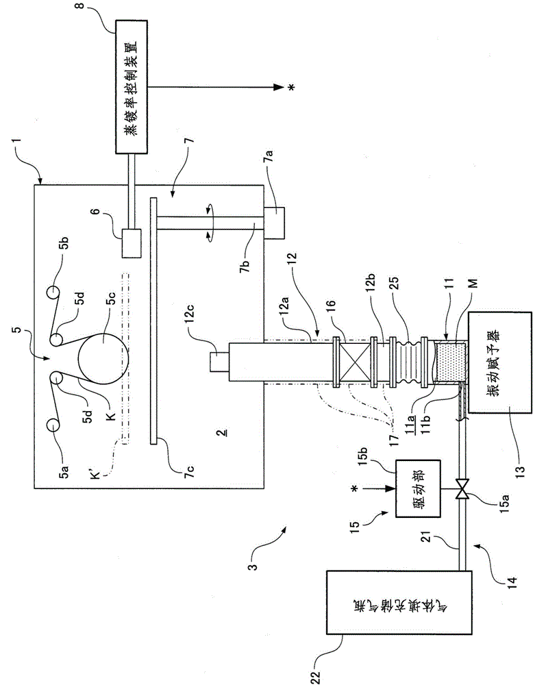
[0091] The vacuum vapor deposition apparatus according to Embodiment 1 of the present invention will be described below with reference to the drawings.
[0092] like figure 1 As shown, the vacuum evaporation device includes a container for evaporation (also referred to as a container for film formation or a vacuum chamber) 1 and a material supply device 3 . The evaporation container 1 has an evaporation chamber (also referred to as a film-forming chamber) 2, and the evaporation chamber 2 is used in a predetermined vacuum environment (for example, 10 -5 In a high vacuum environment below Pa) the vapor deposition material M is attached to the surface (lower surface) of a film-shaped substrate (specifically, a film) K as a member to be vapor deposited to form a thin film. The material supply device 3 supplies (guides) the vapor deposition material M to the vapor deposition container 1 , that is, supplies (guides) the vapor deposition material M to the vapor deposition chamber 2 ...
Embodiment 2
[0138] Next, a vacuum vapor deposition apparatus according to Example 2 of the present invention will be described with reference to the drawings.
[0139] In the above-mentioned Example 1, the vibration imparter (vibration mechanism) was used to vibrate the material filling container, but the vacuum vapor deposition apparatus of this Example 2 agitates the inside of the material filling container instead of vibration.
[0140] Because the different parts of the vacuum evaporation device of the present embodiment 2 and the embodiment 1 are the parts of the material filling container, the present embodiment 2 focuses on this part, and the same reference numerals are attached to the same components as the embodiment 1 and A detailed description thereof is omitted.
[0141] Briefly, in the material moving path changing pipe 61 described in the first embodiment, a stirring device (stirring mechanism) capable of stirring the vapor deposition material in the material filling contain...
Embodiment 3
[0163] Hereinafter, the vacuum evaporation apparatus of Example 3 of the present invention will be described with reference to the drawings.
[0164] like Figure 9 As shown, the present vacuum evaporation device includes a container for evaporation (also referred to as a container for film formation or a vacuum chamber) 101 and a material supply device 103 . The evaporation container 101 has an evaporation chamber (also referred to as a film forming chamber) 102, and the evaporation chamber 102 is used in a predetermined vacuum environment (for example, 10 -5 In a high vacuum environment below Pa) the vapor deposition material M is attached to the surface (lower surface) of a film-shaped substrate (specifically, a film) K as a member to be vapor deposited to form a thin film. The material supply device 103 supplies (guides) the vapor deposition material M to the vapor deposition container 101 , that is, the vapor deposition chamber 102 .
[0165] First, the internal structu...
PUM
 Abstract
Description
Claims
Application Information