Electrodes of a Fuel Cell

a fuel cell and electrode technology, applied in the field of electrodes of fuel cells, can solve the problems of nickel mesh being prone to breakage, high cost, electrical loss, etc., and achieve the effects of high gas pressure, simple fuel cell, and high efficiency

Active Publication Date: 2009-09-17
AFC ENERGY
View PDF20 Cites 18 Cited by
  • Summary
  • Abstract
  • Description
  • Claims
  • Application Information

AI Technical Summary

Benefits of technology

[0042]The fuel cell assembly of the invention is advantageously arranged so that, in operation, the gases in the gas chambers may be maintained at a positive pressure for example of at least +1 kPa such as approximately +2 kPa. Preferably, the fuel cell assembly includes a gas pressure regulator for maintaining the gases in the gas chambers at positive pressures during operation. The pressure of the fuel gas and the oxidant gas may be the same or they may be different. The provision of gas at a positive pressure assists the flow of gases to the gas chambers of the fuel cell to replace gas consumed in the chemical reactions of the cell, so for example the air may be supplied at 2.5 kPa such that the pressure is 2.0 kPa in the gas chamber and at 1.5 kPa at the outlet. A positive pressure of approximately +2 kPa has been found to be sufficient to supply gas flow to the gas chambers for both a fuel-gas and an oxidant-gas. Alternatively the fuel cell may be so arranged that the gas in the gas chamber is maintained at atmospheric pressure, the entire pressure differential being provided by the negative electrolyte pressure. Preferably the fuel cell is arranged so that in operation the gas is at a low positive pressure of no greater than +8 kPa and more preferably no greater than +5 kPa. The provision of gases at relatively low pressures allows the construction of fuel cells to be simpler than those needing to withstand high gas pressures. Furthermore, the reduced need to provide gases at high pressure in the fuel cell assemblies of the invention may allow them to be run more efficiently than prior-art assemblies in which a considerable amount of energy is required to run compressors and the like to maintain high gas pressures.
[0043]The containing of gases at high pressures (for example, a pressure of approximately +10 kPa) poses technical problems that constrain the design of fuel cell assemblies. In particular, the containing of fuel gases such as hydrogen, which permeate relatively easily through barriers at high pressures, is not straightforward. In order to accommodate gases at high pressures without leaking a fuel cell requires a complicated design and / or careful construction, for example with appropriate seals that are not permeable to high pressure fuel gases. The fuel cell assemblies of the present invention that are operated with a pressure differential between the electrolyte and the gases that is at least partly established by maintaining the electrolyte at a negative pressure may circumvent some of the problems associated with designing a fuel cell assembly to withstand high gas pressures. The design of fuel cell assemblies arranged to operate with negative electrode pressures has been found to be more straightforward. The containing of aqueous electrolytes at negative pressures has been found to be more easily achieved than containing gases at high pressures. Furthermore, it enables the pressure differentials between each of the gases and the ambient atmosphere and between the electrolyte and the ambient atmosphere to be modest, which simplifies construction.
[0044]A further advantage of fuel cell assemblies that operate with the electrolyte at a negative pressure is that the concentration of the electrolyte can be more easily controlled. Preferably the concentration of the electrolyte is controlled by adjusting the electrolyte pressure. For example, when the electrolyte is KOH it has been found that lowering the KOH pressure (so it is more negative) causes the KOH concentration to decrease (as more water is drawn in from the anode), which in turn causes the vapour pressure to rise and that increases the rate of evaporation. As the vapour pressure is affected by concentration and temperature, and affects the evaporation rate, the KOH pressure can be used to control the KOH concentration balance. As the concentration of electrolyte (KOH) increases, the vapour pressure of water above it falls. This provides a convenient means of control. Thus at a suitable temperature, say 60° C., water from the reaction from the oxidation of hydrogen at the anode will evaporate from the cathode (air electrode) until a constant concentration is achieved. Provided that the air flow is proportional to the current drawn from the cell, stability will result. It will be appreciated that a similar result is to be expected with other electrolytes.

Problems solved by technology

Such electrodes are expensive, electrically lossy, thick, heavy and suffer from irregular distribution of catalyst.
Furthermore, the nickel mesh is prone to breakage and causes local irregularities and unwanted variations in electric field due to resistance at the contact points between the wires of the mesh.
A problem with many known fuel cell assemblies is that liquids (typically water), that are a product of the chemical reactions occurring at the electrodes, are trapped in the gas chambers, and the liquid has to be removed from the gas chambers by a water management system including pumps, dehumidifiers, drainage channels or the like adding to the complexity of fuel cells.
The loss of liquid reaction products from the electrolyte chamber also means that the electrolyte needs to be constantly topped up either with recycled lost liquid or additional fresh liquids.
Furthermore, the presence of the liquid reaction products (especially water) in the fuel cells reduces the capability of fuel cells to operate at low temperatures approaching the freezing point of the liquids.
Furthermore, the Porvic® plastic material is hydrophobic (requiring alcohols such as n-propanol or n-butanol in order to wet the substrate) and so aqueous electrolytes are not readily absorbed into the pores of the electrode substrate.

Method used


Image

  • Electrodes of a Fuel Cell
  • Electrodes of a Fuel Cell
  • Electrodes of a Fuel Cell

Examples


example 1

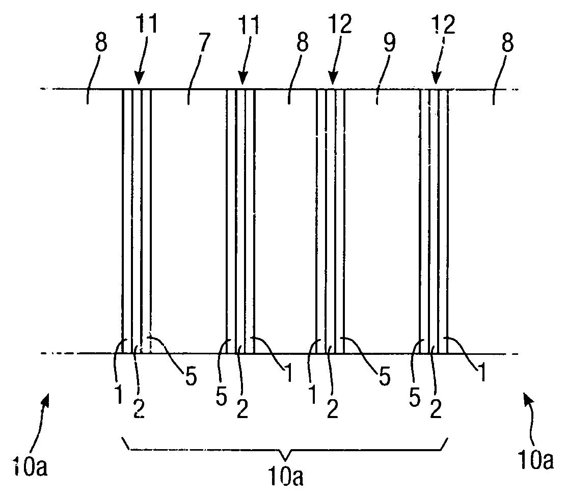
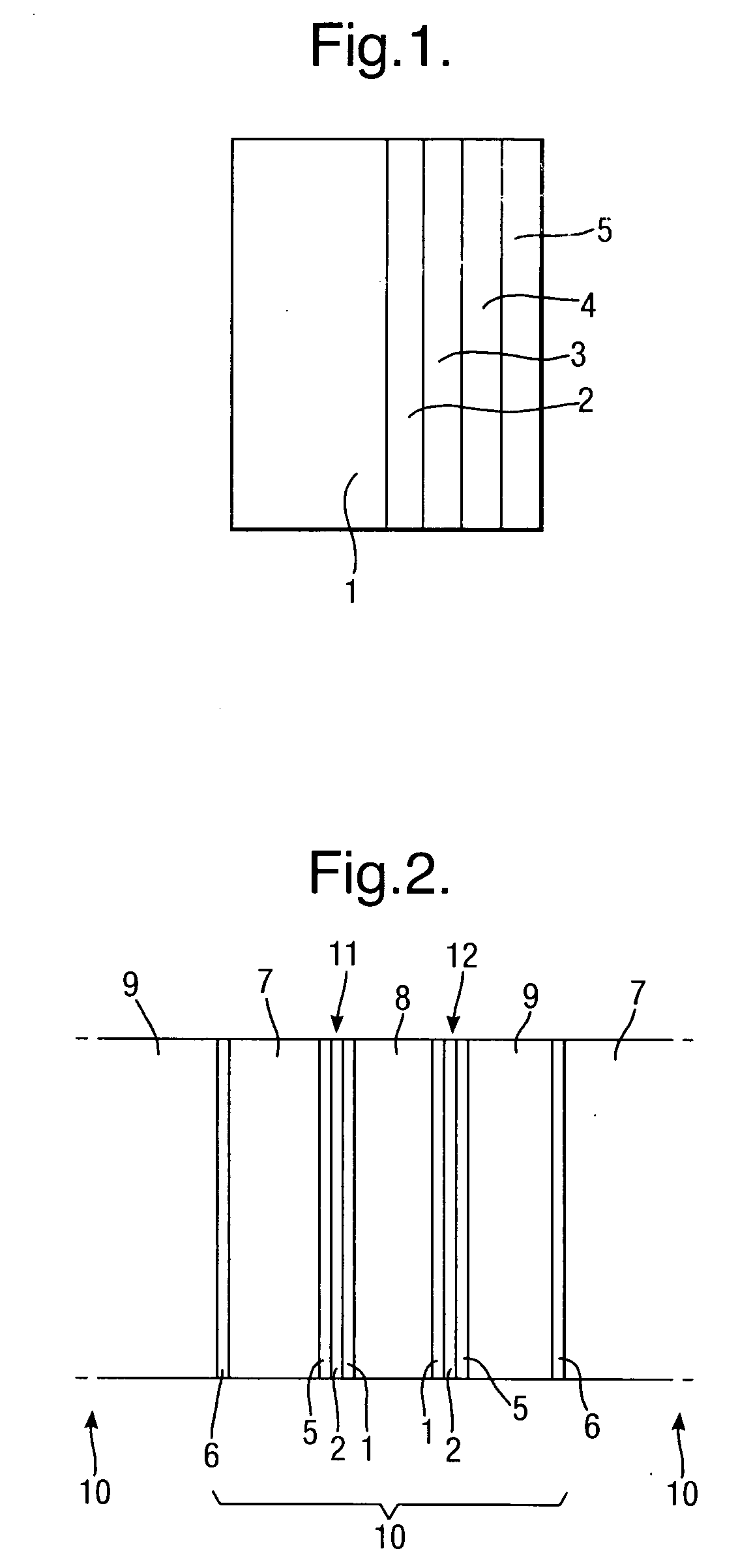
[0054]A 0.5 μm layer of silver is electro-less plated onto the substrate 1 to form a first layer 2 of conductive material. A second layer 3 of silver of thickness 3 μm is then electroplated onto the first layer 2 of conductive material. A protective 0.05 μm thick layer 4 of rhodium is then electroplated onto the second layer 3 of conductive material to complete the conductive layer structure.

example 2

[0055]A 0.5 μm layer of silver is electro-less plated onto the substrate 1 to form a first layer 2 of conductive material, followed by electroplating copper to form a second layer 3 of thickness 5 μm of conductive material, followed by electroplating a protective layer 4 of nickel, 1 μm thick.

example 3

[0056]A 0.5 μm layer 2 of silver is electro-less plated onto the substrate 1 to form a first layer of conductive material, followed by electroplating 5 μm thickness of nickel to form a second layer 3 of conductive material.

The Catalyst Mixture

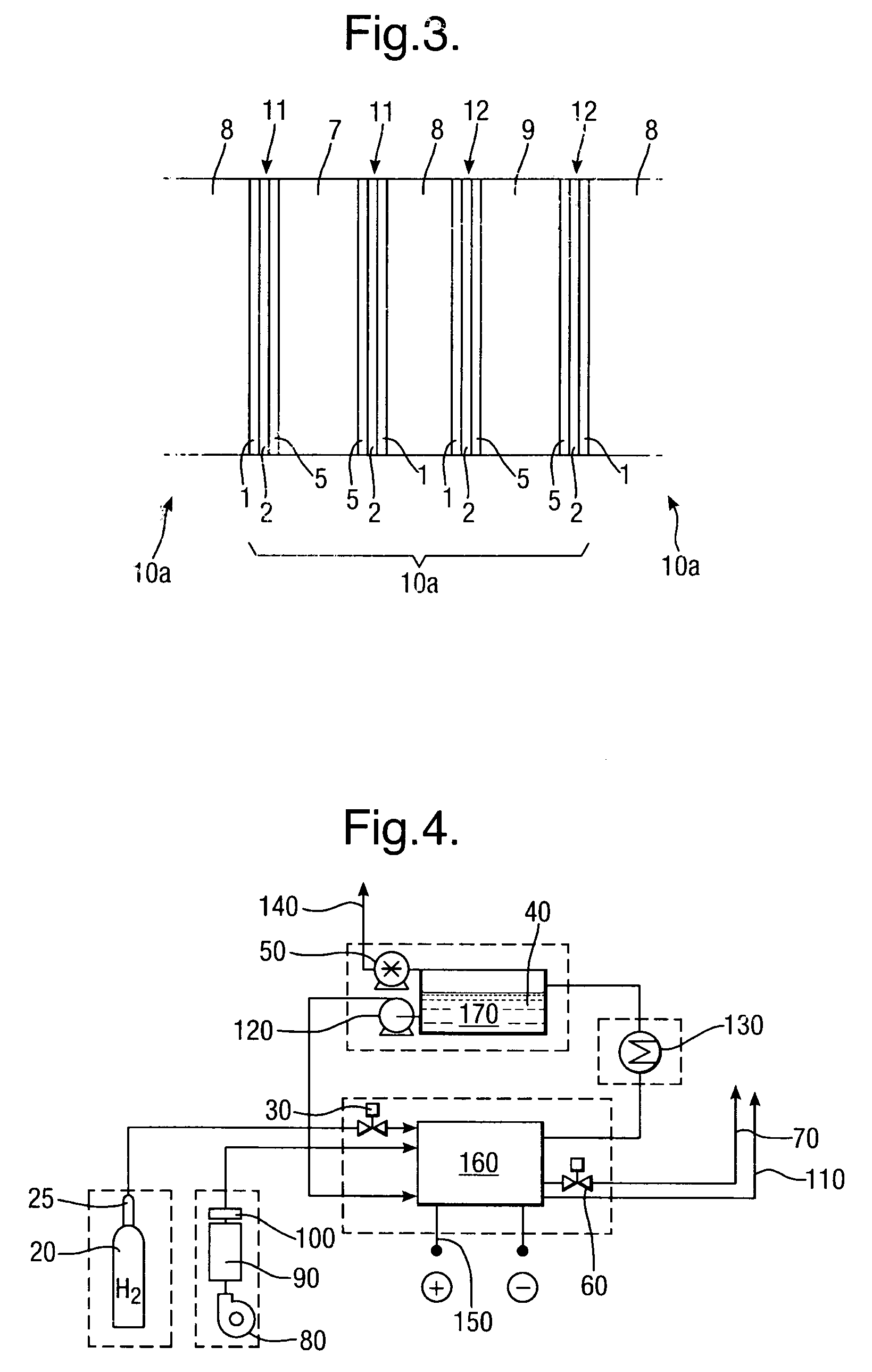
[0057]The example catalyst mixtures for both cathode and anode electrodes use a combination of catalyst, binder and solvent which are spray-coated onto the conductor layers of Examples 1, 2 and 3 above. The binder may for example be polyethylene (such as PE1020 from Exxon-Mobil), and the solvent isododecane. Percentage weights refer to the total mass of the dry materials before the addition of a suitable solvent.

[0058]The cathode catalyst mixtures A to C below include an oxygen reduction catalyst.[0059]A. Activated carbon, with 10% binder and solvent.[0060]B. 10% Pd / Pt on activated carbon, with 10% binder+solvent.[0061]C. Silver on activated carbon, with 10% binder+solvent.

[0062]The anode catalyst mixtures D and E below include a hydrogen oxida...


PUM

PropertyMeasurementUnit
thicknessaaaaaaaaaa
contact angleaaaaaaaaaa
water contact angleaaaaaaaaaa

Abstract

An electrode for use in a fuel cell consists of a porous plastic substrate, a conductive layer and a catalyst layer, in which the substrate is hydrophilic. Preferably the substrate has a water wicking rate no less than 40 mm per 600 s. Such an electrode may be used in a fuel cell, with an electrolyte chamber (8) defined between two opposed electrodes (11, 12), the electrodes having the catalyst layers (5) facing away from the electrolyte in contact with respective gas chambers (7, 9). Preferably the electrolyte is maintained at a negative pressure during operation.

Description

[0001]The present invention relates to electrodes that may be used in fuel cells, preferably but not exclusively alkaline fuel cells and also to fuel cell assemblies including the electrodes.BACKGROUND TO THE INVENTION[0002]Fuel cells have been identified as a relatively clean and efficient source of electrical power. Alkaline fuel cells are of particular interest because they operate at relatively low temperatures, are efficient and rugged. Acid fuel cells and fuel cells employing other aqueous electrolytes are also of interest. Such fuel cells typically comprise an electrolyte chamber separated from a fuel gas chamber (containing a fuel gas, typically hydrogen) and a further fuel gas chamber (containing an oxidant gas, usually air). The electrolyte chamber is separated from the gas chambers using electrodes. Typical electrodes for alkaline fuel cells comprise a conductive metal grid or mesh backbone, typically nickel, that provides mechanical strength to the electrode. Onto the me...

Claims


Application Information

Patent Timeline
Patent Type & Authority Applications(United States)
IPC IPC(8): H01M2/14H01M8/02
CPCH01M4/86H01M4/92H01M4/923H01M4/926Y02E60/50H01M8/04089H01M8/04223H01M8/04276H01M8/083H01M8/0273H01M8/0271H01M8/241
Inventor CARLISLE, OTTO F.SAUER, GERARD P.T.
Owner AFC ENERGY
Why Eureka
Try Eureka