
Collective doffing gear block steel belt guide mechanism of ring spinning frame

A spinning frame and steel belt technology, applied in the direction of textiles and papermaking, etc., can solve the problems that the steel belt is not easy to elongate, the guiding effect is not good, and the positioning accuracy is low, so as to ensure high stability and reliability, stable transportation, The effect of fast delivery

Pending Publication Date: 2016-02-10
JINGWEI TEXTILE MASCH CO LTD
View PDF11 Cites 0 Cited by
  • Summary
  • Abstract
  • Description
  • Claims
  • Application Information

AI Technical Summary

Problems solved by technology

One is that the steel belt adopts friction transmission and is guided by the outer edge of double guides. This technology has good guiding effect, accurate positioning, and small guide rail resistance, but the tension required by friction transmission is large, and the steel belt is easy to elongate. Cause the transmission to slip, and then fail
The other is that the steel belt is driven by gear blocks, and the inner side of the single guide is floating. Slip, the disadvantage is that the guiding effect is not good, the resistance of the guide rail is large, the positioning accuracy is low, and it is easy to cause the misalignment of the convex plate, resulting in low reliability of the system

Method used


Image

  • Collective doffing gear block steel belt guide mechanism of ring spinning frame
  • Collective doffing gear block steel belt guide mechanism of ring spinning frame

Examples


Embodiment Construction

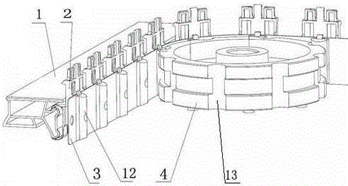
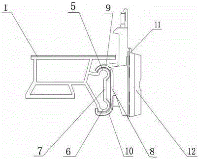
[0010] Such as figure 1 As shown, a ring spinning frame collective doffing gear steel belt guide mechanism, which includes a steel belt guide rail 1, a convex disc bracket 2, a transmission steel belt 3, and a driving wheel 4. The steel belt guide rail 1 is provided with an upper guide The outer edge 5 and the lower guide outer edge 6, the upper guide outer edge 5 and the lower guide outer edge 6 are circular arc structures protruding outward, the upper guide outer edge 5 is located directly above the lower guide outer edge 6, and the upper guide outer edge 5 is located directly above the lower guide outer edge 6. The outer edge 5 and the lower guide outer edge 6 are integrally formed by a vertical rib plate 7, and a "C"-shaped covering structure 8 is arranged on the convex plate bracket 2, and the two sides of the "C"-shaped covering structure 8 The ends are respectively an upper guide buckle 9 and a lower guide buckle 10 of a groove-shaped structure, and the upper guide buck...


PUM


Abstract

The invention relates to a collective doffing gear block steel belt guide mechanism of a ring spinning frame. Upper guide outer fringes and lower outer fringes are arranged on a steel belt guide rail, the upper guide outer fringes and the lower outer fringes are each of a circular-arc-shaped structure protruding outwards, each upper guide outer fringe is located over the corresponding lower guide outer fringe, each upper guide outer fringe and the corresponding guide outer fringe are integrally formed through a vertical ribbed plate, and each upper guide outer fringe and the corresponding lower guide outer fringe are coated with an upper guide buckle and a lower guide buckle in a slidable and matched mode respectively; a vertical long-strip structure is arranged on each protruding disc bracket, one side of a transmission steel belt is provided with an insertion slot, a transmission gear block shaped like a semicircular cylinder is arranged on the other side of each transmission steel belt, each insertion slot is installed on the corresponding long-strip structure in an inserted mode to fix the corresponding transmission steel belt to the corresponding protruding disc bracket, arc-shaped grooves are formed in the circumferential surface of a driving wheel, the gear blocks of the transmission steel belts are connected with the arc-shaped grooves, and the transmission steel belts are driven to conduct transmission through rotation of the driving wheel. By means of the collective doffing gear block steel belt guide mechanism of the ring spinning frame, high stability and reliability of a system can be guaranteed, and the highly automatic requirement of textile industry is met.

Description

technical field [0001] The invention belongs to a component of textile machinery, and in particular relates to a collective doffing tooth block steel belt guide mechanism of a ring spinning frame. Background technique [0002] With the development of the textile industry, the collective doffing spinning frame has become the mainstream of industry demand, and the convex disc conveying technology is the core technology in the collective doffing system. There are two kinds of existing pallet conveying technologies, one is cylinder reciprocating push-pull pallet conveying technology, and the other is steel belt pallet conveying technology. Domestic spinning frame manufacturers mostly use cylinder reciprocating push-pull tray conveying technology. The advantages of this technology are simple structure and low manufacturing cost; the disadvantages are high requirements on the quality of the convex disc, short service life, heavy maintenance workload, high failure rate, and reliabl...

Claims


Application Information

Patent Timeline
Patent Type & Authority Applications(China)
IPC IPC(8): D01H9/18
Inventor 田克勤谈叡王建根龚锦尹利雄邓靖郭金燕李嘉琦张丽萍张满枝苏旭华
Owner JINGWEI TEXTILE MASCH CO LTD
Learn More