
Fan assembly and fan frame thereof

A fan assembly and fan frame technology, which is applied to pump components, parts of pumping devices for elastic fluids, non-variable pumps, etc., to achieve the effect of reducing noise and reducing noise

Active Publication Date: 2016-02-10
DELTA ELECTRONICS INC
View PDF6 Cites 12 Cited by
  • Summary
  • Abstract
  • Description
  • Claims
  • Application Information

AI Technical Summary

Problems solved by technology

[0004] In view of the above problems, the purpose of the present invention is to provide a fan assembly and fan frame, which can maintain the performance of the fan assembly itself and improve the noise problem caused by the flow field through a novel and simple structural design

Method used


Image

  • Fan assembly and fan frame thereof
  • Fan assembly and fan frame thereof
  • Fan assembly and fan frame thereof

Examples


Embodiment Construction

[0047] A fan assembly and a fan frame according to preferred embodiments of the present invention will be described below with reference to related drawings, wherein the same elements will be described with the same reference symbols.

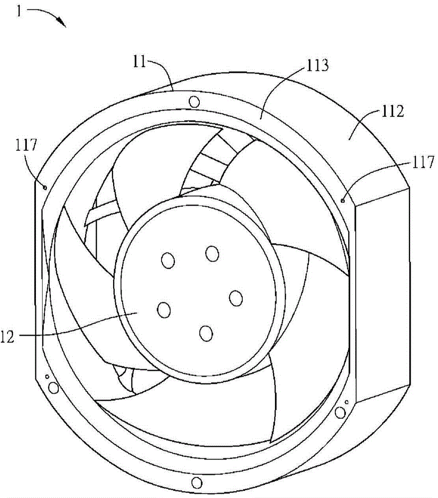
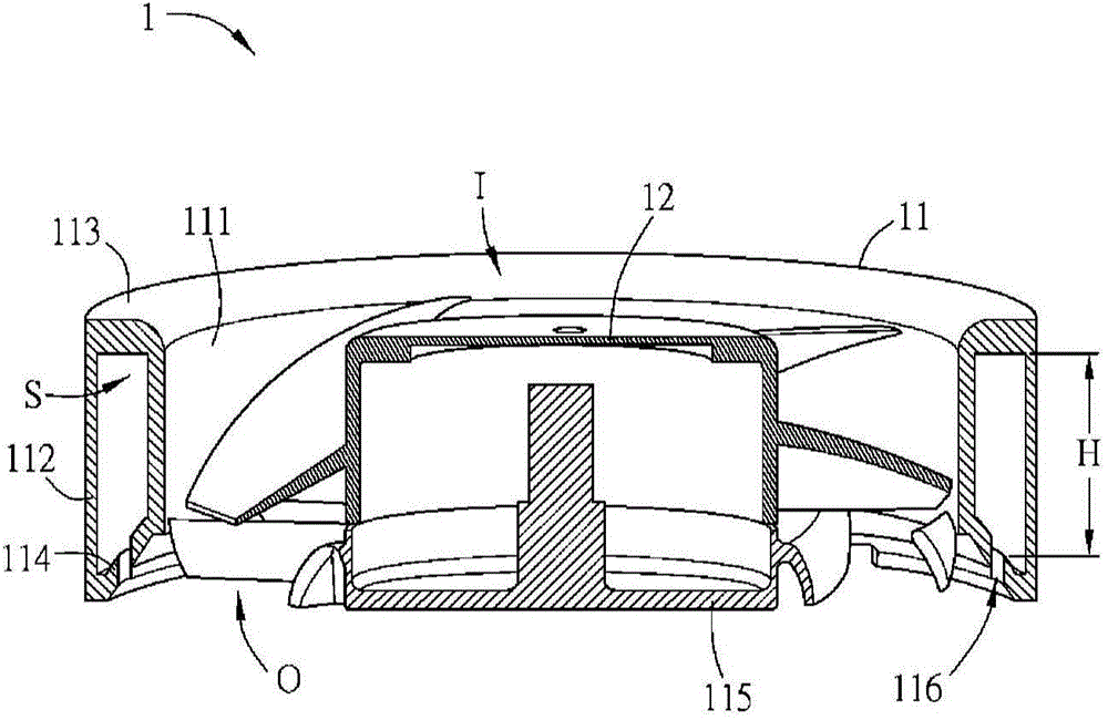
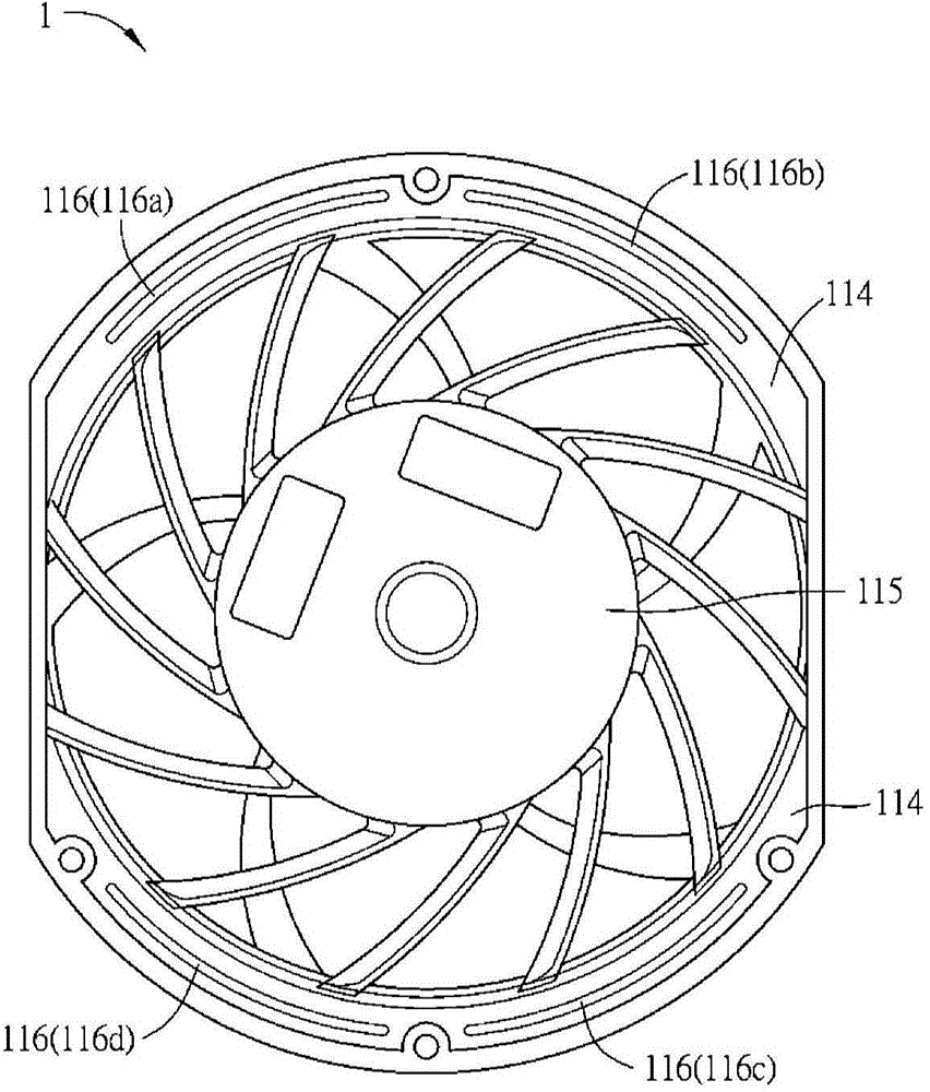
[0048] figure 1 is a schematic diagram of a fan assembly according to an embodiment of the present invention, figure 2 for figure 1 A schematic cutaway of the fan assembly is shown. Such as figure 1 and figure 2 As shown, the fan assembly 1 includes a fan frame 11 and an impeller 12 . When the fan assembly 1 is in operation, an air inlet port I can be formed at one end of the fan frame 11, and an air outlet port O is formed at the other end, that is, the fan frame 11 has an air inlet port I and an air outlet port O. The operation of the fan assembly 1 is driven by the motor to drive the impeller 12, which is common knowledge in the technical field of the present invention, so it will not be described in detail. In this embodiment, the f...


PUM


Abstract

The invention provides a fan assembly and a fan frame thereof. The fan frame is provided with an air inlet end and an air outlet end and comprises a side wall, a top and a bottom; the top is connected to one end of the side wall and is close to the air inlet end, and the bottom is connected to the other end of the side wall, is close to the air outlet end and is provided with at least one noise reducing structure. An impeller is arranged in the fan frame.

Description

technical field [0001] The invention relates to a fan assembly, in particular to a fan frame of the fan assembly. Background technique [0002] Generally speaking, it is difficult to avoid the generation of noise when the fan is running, so how to solve the noise problem when the fan is running is the research and development of the fan and the industry. The reason for the noise may be the noise generated by the airflow disturbance (or flow field) from the air inlet end and the air outlet end of the fan; or the noise caused by the vibration of the fan as a whole when the fan is running. As for the noise generated by vibration, it can reduce the effect of noise by designing a buffer structure or strengthening the bonding strength between components. [0003] However, the noise generated at the air inlet and air outlet due to airflow disturbance is more obvious, and cannot be overcome by cushioning structures or strengthening the bonding strength, so it is even more difficult...

Claims


Application Information

Patent Timeline
Patent Type & Authority Applications(China)
IPC IPC(8): F04D29/52F04D29/66
CPCF04D19/002F04D25/0613F04D29/522F04D29/663F04D29/665
Inventor 张楯成杨朝富
Owner DELTA ELECTRONICS INC
Learn More