
drone

A technology of drones and wings, which is applied in the direction of wing adjustment, aircraft parts, aircraft control, etc., can solve the problems of inflexible adjustment of induced drag and longitudinal lift of drone wings, and achieve the reduction of total resistance and the improvement of flight range. The effect of increasing and improving flexibility

Active Publication Date: 2022-01-07
北京北航天宇长鹰无人机科技有限公司
View PDF12 Cites 1 Cited by
  • Summary
  • Abstract
  • Description
  • Claims
  • Application Information

AI Technical Summary

Problems solved by technology

[0003] In the process of realizing the present invention, the applicant found that the winglets in the traditional technology are all fixed settings, and the induced drag and longitudinal lift of the UAV wings cannot be flexibly adjusted

Method used


Image

  • drone
  • drone
  • drone

Examples


Embodiment Construction

[0037] The invention provides a winglet, which not only reduces the induced resistance of the drone, but also can control the heading attitude of the drone according to the combined deflection of the upper and lower winglets, replacing the role of the rudder of the drone.

[0038] In order to make the object, technical solution and advantages of the present invention clearer, the present invention will be further described in detail below in combination with specific embodiments and with reference to the accompanying drawings.

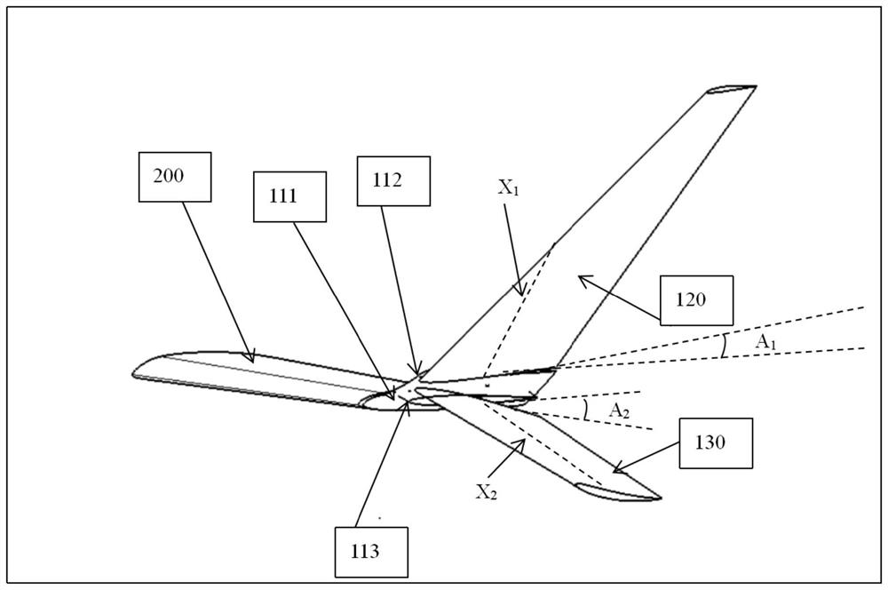
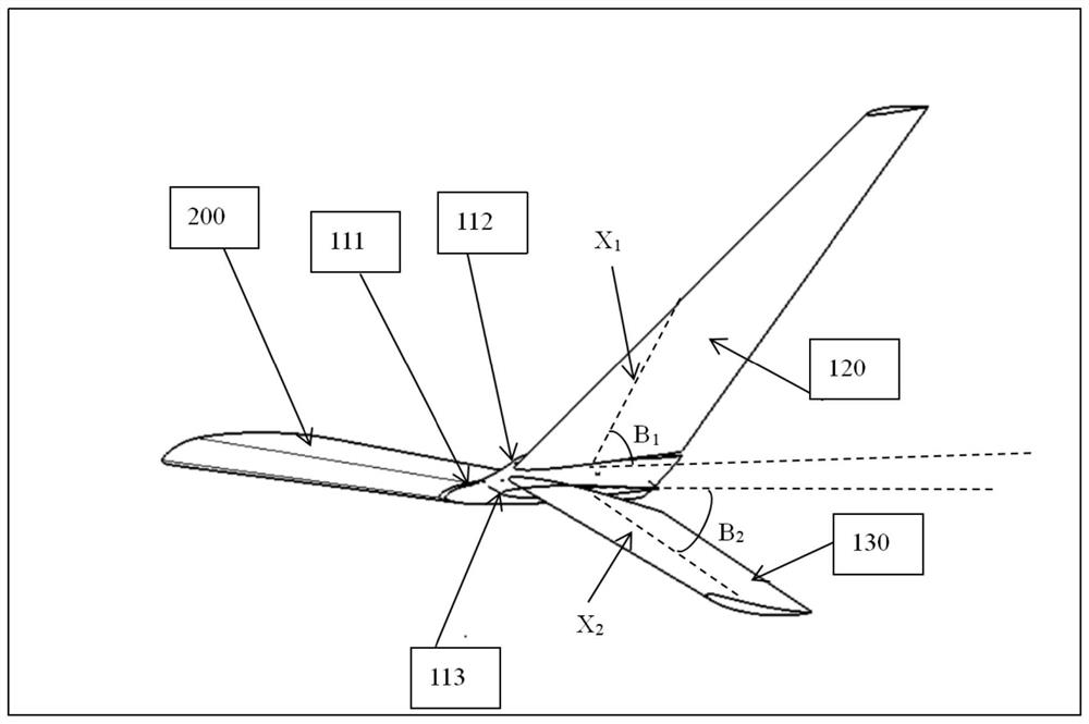
[0039] The present invention firstly provides a winglet. The winglet has a rotatable upper winglet and a lower winglet, so that the induced drag and longitudinal lift of the wing can be flexibly adjusted.

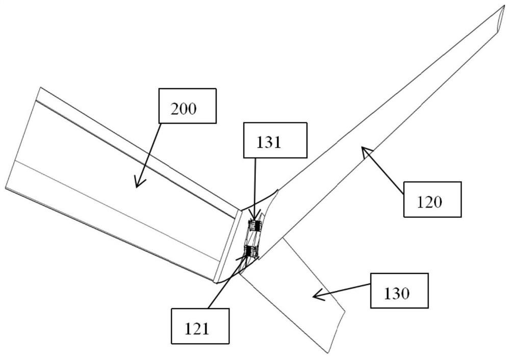
[0040] figure 1 and figure 2 It is a perspective view of an embodiment of the winglet of the present invention. Please refer to figure 1 and figure 2 In this embodiment, the winglet is fixed on the distal end of the wing body 200, including: ...


PUM


Abstract

The invention provides an unmanned aerial vehicle. Among them, the deflection of the upper and lower winglets of the winglet around its own axis not only reduces the induced drag of the UAV wing, but also can offset the change of longitudinal lift according to the combined deflection of the upper and lower winglets to control the UAV. The man-machine heading, which plays the role of the rudder of the UAV, has the effect of killing two birds with one stone. It has broad application prospects in the field of UAVs and traditional fixed-wing UAVs.

Description

technical field [0001] The invention relates to the technical field of aircraft airfoil design, in particular to an unmanned aerial vehicle. Background technique [0002] The lift of the drone comes from the pressure difference between the upper and lower surfaces of the wing, but near the wingtip, because there is no division of the wing, the high-pressure airflow of the lower wing will flow around the wingtip to the upper surface, thus forming the "lift" By-product" - wingtip vortex, wingtip vortex will weaken part of the lift of the wingtip, and then generate induced drag, affecting the stability of the UAV. The winglet is like a wall, which can hinder the upward flow of high-pressure airflow on the lower wing, weaken the wingtip vortex, reduce the induced resistance of the drone, reduce fuel consumption, and improve the range. [0003] In the process of realizing the present invention, the applicant found that the winglets in the traditional technology are all fixed, an...

Claims


Application Information

Patent Timeline
Patent Type & Authority Patents(China)
IPC IPC(8): B64C3/38B64C23/06
CPCB64C3/38B64C23/069Y02T50/10
Inventor 任勇勇熊阳王靖欢
Owner 北京北航天宇长鹰无人机科技有限公司
Learn More