Inner rzeppa shell and outer rzeppa shell connected forging and forging die for same

A technology of inner ball cage and outer ball cage, which is used in manufacturing tools, forging/pressing/hammer devices, forging/pressing/hammering machinery, etc. Incomplete outer side walls and other problems, to achieve the effect of significant energy saving and consumption reduction, lower scrap rate and high assembly efficiency

Active Publication Date: 2016-02-10
SHANGHAI GKN DRIVE SYST
View PDF7 Cites 4 Cited by
  • Summary
  • Abstract
  • Description
  • Claims
  • Application Information

AI Technical Summary

Problems solved by technology

[0003] The outer cage part of the prior art conjoined forging of inner and outer cages is basically formed; restricted by the forging die, the center hole of the inner cage part has not been forged, and the outer wall is also very incomplete. After the forging process, it must be Then the machining process can process the center hole and the outer wall of the inner ball cage, so the production process is complicated, and the production cost of the inner and outer ball cages is high.
Moreover, during the machining process of the center hole and the outer wall of the inner ball cage, a lot of waste will be generated, so the material consumption is large and the material utilization rate is low
However, the die cores of the forging dies of the prior art inner and outer spherical cage conjoined forgings often adopt an integrated structure, the forging forming surface of the only upper die core is the upper end face of the inner and outer spherical cage conjoined forgings, and the only lower die The forging forming surface of the core is the lower end surface of the inner and outer spherical cage conjoined forgings. The forging forming surface of the upper mold core and the forging forming surface of the lower mold core are both stepped surfaces with complex shapes. Local damage to the stepped surface will cause The entire mold core is scrapped, so the service life of the mold is short and the use cost is high

Method used


Image

  • Inner rzeppa shell and outer rzeppa shell connected forging and forging die for same
  • Inner rzeppa shell and outer rzeppa shell connected forging and forging die for same
  • Inner rzeppa shell and outer rzeppa shell connected forging and forging die for same

Examples


Embodiment Construction

[0058] The implementation of the present invention will be illustrated by specific specific examples below, and those skilled in the art can easily understand other advantages and effects of the present invention from the contents disclosed in this specification.

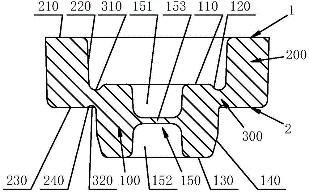
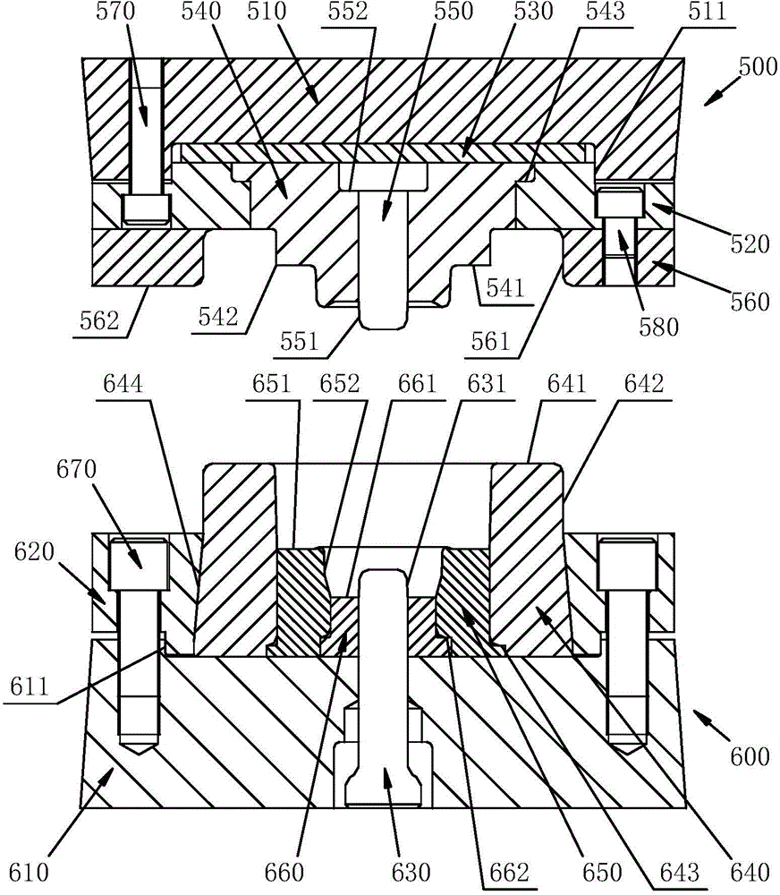
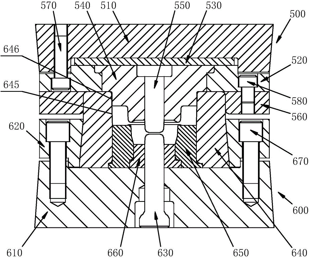
[0059] see Figure 1 to Figure 4 . It should be noted that the structures, proportions, sizes, etc. shown in the drawings attached to this specification are only used to match the content disclosed in the specification, for those who are familiar with this technology to understand and read, and are not used to limit the implementation of the present invention. Limiting conditions, so there is no technical substantive meaning, any modification of structure, change of proportional relationship or adjustment of size, without affecting the effect and purpose of the present invention, should still fall within the scope of the present invention. The disclosed technical content must be within the scope covered. At the sa...


PUM

PropertyMeasurementUnit
thicknessaaaaaaaaaa

Abstract

The invention provides an inner rzeppa shell and outer rzeppa shell connected forging. The upper end surface of the forging comprises an outer rzeppa shell upper end surface, an outer rzeppa shell upper side inner wall, a connecting part upper end surface, an inner rzeppa shell upper side outer wall and an inner rzeppa shell upper end surface; the lower end surface of the forging comprises an outer rzeppa shell lower end surface, an outer rzeppa shell lower side inner wall, a connecting part lower end surface and an inner rzeppa shell lower side outer wall; the forging further comprises an inner rzeppa shell central hole. The invention further provides a forging die for manufacturing the forging. An upper die assembly of the die comprises a split type male die formed by a male die ring and a male die core, the lower end of the male die ring forms a forming surface of the upper end surface of the forging, and the lower end of the male die core forms a forming surface of the upper side wall of the central hole of the inner rzeppa shell; a lower die assembly comprises an ejection rod and a split type female die formed by a female die outer ring, a female die middle ring and a female die inner ring, the upper end of the split type female die forms forming surfaces of the lower end surface of the forging and the outer side wall of the outer rzeppa shell, and the upper end of the ejection rod forms a forming surface of the lower side wall of the central hole of the inner rzeppa shell. The utilization rate of raw materials of the forging is high, and the production cost of the inner rzeppa shell and the outer rzeppa shell is low.

Description

technical field [0001] The invention relates to the technical field of manufacturing inner and outer ball cages of a ball cage type mobile universal joint, in particular to an inner and outer ball cage connected forging and a forging mold thereof. Background technique [0002] The ball cage mobile universal joint is an important part of the rear wheel drive of the car, including the inner ball cage and the outer ball cage. The outer diameter of the inner ball cage is smaller than the inner diameter of the outer ball cage. The processing methods of the inner ball cage and the outer ball cage often adopt the forging method. In the past, the forging process of the inner ball cage and the outer ball cage was often carried out independently. Both of them produced a lot of waste during the forging process, and the material consumption was large; and in Before the forging process, the blanks of the outer cage and the inner cage need to be heated separately, resulting in a large ene...

Claims


Application Information

Patent Timeline
Patent Type & Authority Applications(China)
IPC IPC(8): F16D3/223B21J13/02
Inventor 黄声德
Owner SHANGHAI GKN DRIVE SYST
Why Eureka
Try Eureka