
Iron core and motor

A technology of iron core and yoke, applied in the field of motor, can solve problems such as small effective magnetic flux area of ​​iron core

Inactive Publication Date: 2016-02-10
ZHUHAI GREE REFRIGERATION TECH CENT OF ENERGY SAVING & ENVIRONMENTAL PROTECTION
View PDF4 Cites 2 Cited by
  • Summary
  • Abstract
  • Description
  • Claims
  • Application Information

AI Technical Summary

Problems solved by technology

[0004] The present invention aims to provide an iron core and a motor to solve the problem that the effective magnetic flux area of ​​the iron core is small in the prior art

Method used


Image

  • Iron core and motor
  • Iron core and motor
  • Iron core and motor

Examples


Embodiment Construction

[0024] The embodiments of the present invention will be described in detail below with reference to the accompanying drawings, but the present invention can be implemented in many different ways defined and covered by the claims.

[0025] As a first aspect of the present invention, an iron core is provided. Such as Figure 4 to Figure 6 As shown, the iron core includes a body, and there are multiple bodies, and the plurality of bodies are connected end to end in sequence to form a cylinder. On the outer surface of the yoke portion 20, the second end 22 of the yoke portion 20 protrudes to one side of the tooth portion 10 so that the body is L-shaped, and a matching step is formed between the first end 21 of the yoke portion 20 and the outer surface of the tooth portion 10 30. The mating step 30 is the first connection part, the second end of the yoke part 20 is the second connection part, and the first connection part and the second connection part are mated and connected. Si...


PUM


Abstract

The invention provides an iron core and a motor. The iron core comprises a plurality of bodies, and the bodies are orderly connected end to end to be in a cylinder shape. Each body comprises a tooth part and a yoke part. The first end of the yoke part is arranged on the outer surface of the tooth part. The second end of the yoke part is stretched out towards one side of the tooth part, so that the body is in an L shape. A cooperated step is formed between the first end of the yoke part and the outer surface of the tooth part. The cooperated step is a first connecting part, and the second end of the yoke part is a second connecting part. The first connecting part and the second connecting part are connected cooperatively. The first connecting part and the second connecting part are arranged at the relatively thicker part of the yoke part so that the distance between the outer surface of the tooth part and the outer surface of the yoke part is increased. That is to say, the effective magnetic-flow area of the yoke part is increased so that flux density of an iron core is effectively reduced. Furthermore, the iron loss of the motor is lowered, and an overload capability of the motor is improved.

Description

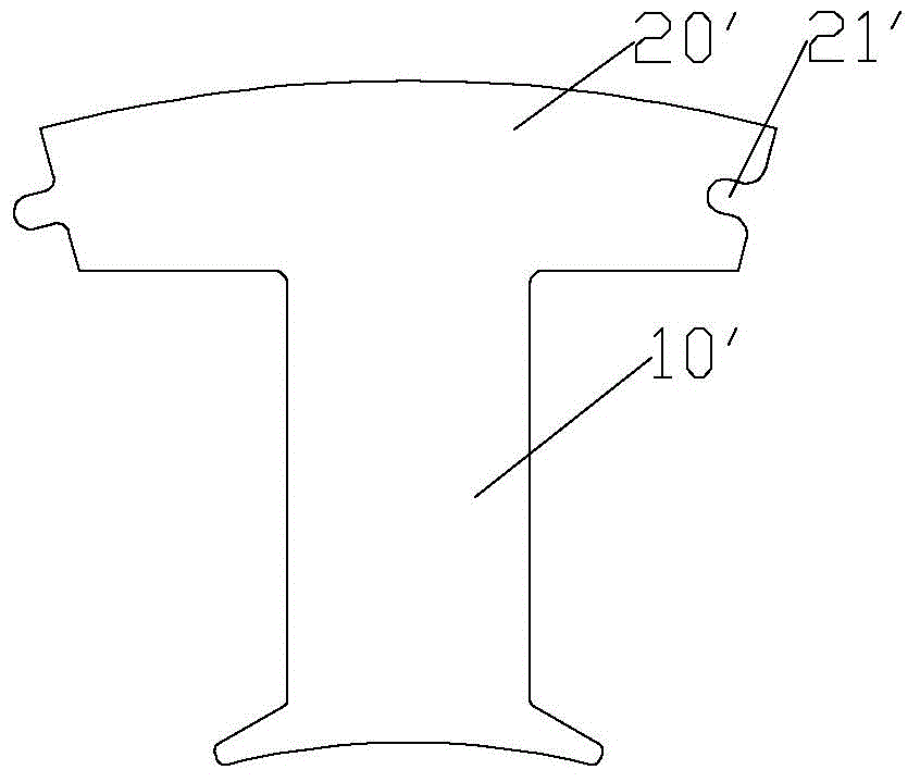
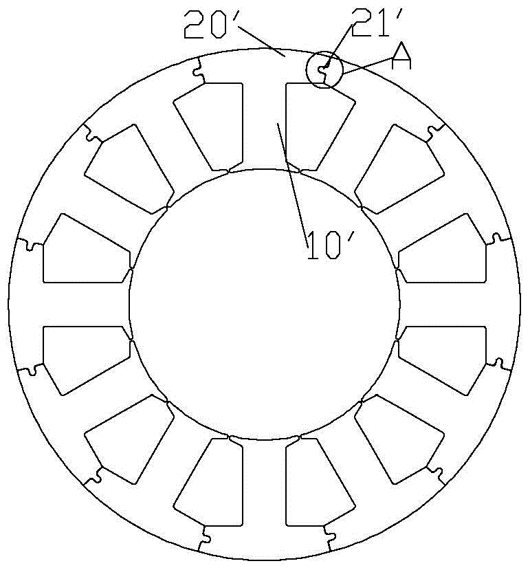
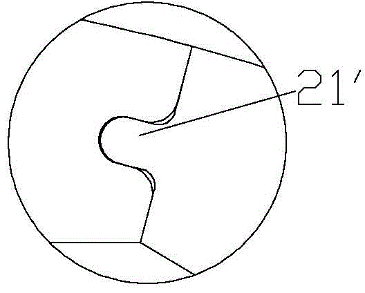
technical field [0001] The present invention relates to the technical field of motors, and more specifically, to an iron core and a motor. Background technique [0002] Such as Figure 1 to Figure 3 As shown, the iron core includes a plurality of bodies, each body includes a tooth portion 10' and a yoke portion 20', and the body is T-shaped, that is, the yoke portion 20' is symmetrically arranged on the tooth portion 10'. The connection part 21' is located at both ends of the yoke part 20'. In order to facilitate winding, the connection part of the yoke part 20' and the tooth part 10' is in a right-angle structure, so that the yoke part 20' gradually becomes thinner toward the two ends along the central position. In order to ensure the assembly reliability of the iron core, it is necessary to reserve a certain gap at the position of the connecting portion 21' in actual production. Since the reluctance of the air gap is much larger than that of the iron core, most of the mag...

Claims


Application Information

Patent Timeline
IPC IPC(8): H02K1/12
Inventor 陈飞龙钟成堡张小波刘娜舒龙龙
Owner ZHUHAI GREE REFRIGERATION TECH CENT OF ENERGY SAVING & ENVIRONMENTAL PROTECTION
Learn More