Method and device for processing radio signal

A radio signal and preprocessing technology, applied in the field of computer programs, can solve the problems of improving reception quality and inability, and achieve the effects of improved processing and high cost performance.

Active Publication Date: 2016-02-10
ROBERT BOSCH GMBH
4 Cites 2 Cited by

AI-Extracted Technical Summary

Problems solved by technology

Furthermore, measures to improve the quality o...

Method used

[0032] In the following description of a number of advantageous embodiments of the present invention, the same or similar reference signs are u...

Abstract

The invention relates to a method (700) for processing radio signals (105). The method (700) includes the step of reading (710) of a data block (155), the data block having multiple data values (145) each of which corresponds to one value of radio signals (105) sampled during a preset limited period of time. Moreover, the method (700) includes the step of analyzing (720) the multiple data values (145) of the data block (155) to determine processing parameters (225). The method (700) further includes the step of demodulating (730) each data value (145) of the data block (155) by means of processing rules (235, 410, 420) associated with the processing parameters (225) to process the radio signals (105).

Application Domain

Multiple modulation transmitter/receiver arrangements

Technology Topic

Data valueAlgorithm +1

Image

  • Method and device for processing radio signal
  • Method and device for processing radio signal
  • Method and device for processing radio signal

Examples

  • Experimental program(1)

Example Embodiment

[0032] In the following description of multiple advantageous embodiments of the present invention, the same or similar reference numerals are used for the elements shown in different drawings and having similar functions, in which repeated description of these elements is avoided.
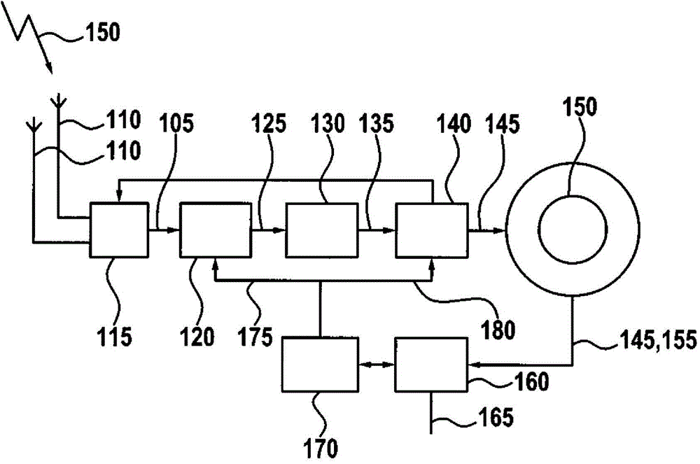
[0033] figure 1 A block diagram of an apparatus 100 for processing a radio signal 105 according to an embodiment of the present invention is shown. The radio signal 105 is here received by one of the plurality of antennas 110, which is selected as the receiving antenna by the corresponding antenna selection switch 115. The radio signal 105 received by the corresponding antenna 110 is then tuned into the HF processing unit 120 for HF (HF: High Frequency) processing, for example, to alias with the corresponding carrier frequency to obtain an intermediate frequency signal or a baseband signal. The signal 125 obtained by the HF processing unit 120 is digitized in an A/D converter, wherein the processed digitized signal 135 thus obtained is realized based on a single sample value of the signal 135. Through such sampling value-based ("sampling-based") processing in the sampling value processing unit 140, it is possible to identify very closely in time, for example, that the signal received by each selected antenna 110 is wrong or strongly interfered. In order to optimize the received radio signal 105 to be analyzed, the sampled value processing unit 140 can now control the antenna selection switch 115, for example, such that the other one of the plurality of antennas 110 is selected for receiving and forwarding radio signals. An antenna is, for example, arranged at another location and therefore has other advantageous optimized reception characteristics for receiving radio signals.
[0034] The sample value of the radio signal (down-aliased) provided by the sample value processing unit 140 is then written into the ring memory 150 as a data value 145. From the ring memory 150, a plurality of data blocks each containing a predetermined number of data values ​​145 are read into the block processing unit 160. In the block processing unit 160, the steps described further below are implemented in a plurality of units constructed accordingly to process the radio signal 105 based on "block-based" processing and provide the information to be extracted contained in the radio signal 105. In addition, multiple control signals can be generated in the block processing unit 160 or the corresponding control software 170, which are read into the HF processing unit 120 and/or the sampled value processing unit 140 and control radio signals in multiple related units 105 or the processing and/or conversion of the signal derived therefrom. For example, the control signal 175 that can be transmitted to the HF processing unit 120 through the block processing unit 160 to the HF processing unit, the control signal aliases the radio signal 105 obtained by the corresponding antenna 110 and other carrier frequencies, so as to be able to process the radio The signal 105 compensates for the slight frequency shift. It is also conceivable that, for example, the control signal 180 from the control software 170 is transmitted to the sampled value processing unit 140 to, for example, realize the temporary amplification of the sampled (aliased) radio signal value present in the signal 135, which is then used as the data value 145 Write to ring memory.
[0035] figure 2 A structural block diagram of the block processing unit 160 is shown. The block processing unit 160 includes an interface 210 for reading in a data block 155, which has a plurality of data values ​​145 corresponding to the values ​​of the radio signal 105 sampled at a predetermined point in time. In addition, the block processing unit 160 includes a unit 220 for analyzing a plurality of data values ​​145 of the data block 155 to determine processing parameters 225. In addition, the block processing unit 160 includes a unit 230 for demodulating each data value 145 of the data block 155 by means of a processing rule 235 according to the processing parameter 225 to process the radio signal 105.
[0036] When the signal processing for the digital modulation type and the analog modulation type can be implemented in the same computing unit, its functions should be completely implemented in software radio receivers (software-defined radio: SDR or software-based receivers: SBR) is advantageous. Based on the system concept, the processing for digital modulation types should be implemented in accordance with multiple embodiments of the "block-based" in the present invention. This means that first a certain number of sample values ​​145 are written into the memory 150, which is then completely processed (in the block processing unit 160) at a certain point in time. The time required for processing is here on average less than the storage time interval of the sample value 145 to be processed. In order to optimize the use of the calculation unit (block processing unit 160), which is particularly advantageous, signal processing for the analog modulation type "block-based" is also implemented. The length of the input memory 150 of each sample value 145 should therefore be located in a similar size (for example, n*8ms).
[0037] image 3 A schematic diagram is shown, in which the calculation cost of the sampling-based signal processing 310 according to the traditional scheme and the block-based signal processing is compared (for example, the DAB processing algorithm 320 or the FM processing algorithm 330 is used as the processing algorithm 235) . The required calculation power R is registered on the vertical axis of the diagram, and the time course t is described on the horizontal axis. by image 3 As shown in the schematic diagram, "sampling-based" signal processing 310 requires continuous small computing power, while DAB processing algorithm 320 or FM processing algorithm 330 as an alternate implementation of processing algorithm 235 requires significantly more computing power. However, at present The signal processing components, such as digital signal processors or microcontrollers, show no major problems.
[0038] In the various proposed embodiments of the present invention, a receiving system for analog and digital modulation types is disclosed, in which analog modulation type signal processing is implemented on a "block basis" like digital modulation type. A simple implementation of the two signal processing on the computing unit is possible here. In addition, the available computing power can be preferably used. The smaller advantage of the solution proposed here is that it can implement a signal replication optimization algorithm, which is not achievable in "sampling-based" processing. Therefore, a complete (data) block 155 can be evaluated (analyzed) and finally determined whether it should be processed again, if necessary, together with other parameters 225.
[0039] figure 1 The description of the embodiment roughly discloses the solution according to the FM receiver such as the one proposed here. In the following description, it should be figure 1 Disclosure of the details of the embodiments. In particular, the HF signal (radio signal 105) received here belongs to the receiving antenna 105 of the HF processing unit 120, and in the processing step, for example, the HF signal 105 is amplified and aliased.
[0040] Then, the signal 125 is continuously transmitted to the analog-to-digital converter 130. The HF processing unit 120 can also be implemented as a so-called wideband converter, where after filtering, the analog-to-digital conversion has the complete frequency range of multiple transmitters. The output value 135 (sample value) of the analog-to-digital converter 130 exists at a fixed sampling rate, that is, a new sample value 135 exists in each time unit (for example, xns). The sampling value 135 is processed in the sampling-based processing unit 140, such as filtering and greatly reducing the sampling rate, which does not allow block-based processing. This belongs to, for example, the control of the antenna switch 115 (for the realization and conversion of the antenna classification).
[0041] In another sample-based processing step, the processed sample value (data value 145) is written to the ring memory 150 by means of a write indicator. The length of the ring memory 150 depends, for example, on the block length of the following block-based processing, the sampling rate used, and the time jitter of the call of the block-based processing. If, for example, starting from a block length of 8 ms and a sampling rate of 400 kHz, at least 8 ms*400 kHz=3200 values ​​(data values) for each block and signal are generated. If the value 145 of the complete block 155 is written into the ring memory, it can be read out and processed by the read indicator. During this time, another new value 145 is written into the ring memory 150 via the write indicator. The reading and processing of the value of the block 155 should be performed faster on average than the writing of the complete block 155. Under normal circumstances, the readout and processing of block 155 proceeds significantly faster than sample-based readout. The length of the ring storage 150 should be at least two blocks in length.
[0042] If the frequency adjustment of the HF processing in the HF processing unit 120 is performed by the receiver control software 170, the value 145 to be written in the ring memory 150 is immediately changed. However, the magnitude of the reception quality, such as the reception field strength or interference information, cannot yet be provided because it is determined by the processing of block 155. Particularly advantageously, the behavior of the receiver control software 170 is synchronized with the write operation of the value in the ring memory 150. Then, for example, after a complete read operation of the block 155 of the ring memory 150, a signal is output, by which the action of the receiver control software 170 is started, which involves the adjustment of the HF processing in the HF processing unit 120.
[0043] The ring memory 150 here includes a memory for status information in addition to a memory used as an input value of the data value 145. If, for example, the frequency adjustment of the HF processing in the HF processing unit 120 is performed by the receiver control software 170, the frequency information is written into the status signal of the ring memory 150. With the aid of the status signal, the status signal corresponding to each value 145 in the ring memory 150 can be determined in the range of the block processing of the block processing unit 160 as to how the corresponding value 145 should be processed continuously. It can then be determined, for example on the basis of the status information, whether to continue the transmission of the value 145 to the signal processing variant 1, 2 or n.
[0044] Figure 4 A block diagram of the components according to such an embodiment of the invention is shown. The analysis of the data values ​​145 of the read-in data block 155 can be implemented in the block processing unit 160 of the analysis unit 220 and the processing parameters 225 can be obtained in addition. The processing parameter 225 can then be used, for example, to control the switch 400 to select one or more signal processing variants or processing algorithms 235, 410, 420.
[0045] According to another embodiment of the present invention, during the so-called replacement frequency test, the HF processing in the HF processing unit 120 during this period is adjusted to the replacement frequency in a short time, and this value thus belongs to the independent signal processing variant 410 Or 420, so that the result 165 (information) can finally be analyzed by the receiver control software 170. The application of the independent signal processing variant 410 or 420 has the advantage that the signal processing value of the replacement frequency is separated from the signal processing value of the current audio of the radio signal 105. In addition, the parameters of the signal processing variant 235, 410 or 420 can be optimized in the corresponding application.
[0046] If it is determined by analyzing the status information to use different signal processing variants 235, 410, or 420, it should be noted that the signal memories for the data blocks 155 used in the different signal processing variants have the same length. This can be achieved by, for example, doubling the value before doubling or increasing a corresponding number of defined values ​​according to the modification of the processing rule used in the block processing unit 160. In addition to selecting signal processing or processing rules used in the block processing unit 160 according to the status signal, multiple signal processing variants 235, 410, or 420 for the block 155 can be implemented in parallel. After processing the complete block 155 (for example using a predetermined preparation) it is determined which signal processing or which processing rule 235, 410 or 420 provides a better result. The result 165 will continue to be transmitted to other multiple processing units.
[0047] Figure 5 A block diagram of multiple components according to this embodiment of the invention is shown, in which this parallel processing of the data value 145 of the data block 155 is replicated by using different processing rules 235, 410 or 420.
[0048] Alternatively or additionally, it is also possible to determine for block 155 after the processing of the signal processing variants 235, 410 or 420, whether the output signal 165 is good enough or whether the calculation or implementation of the processing rules 235, 410 or 420 should be performed with other parameters again Implement. In this case, the signal processing variants 235, 410 or 420 are not always implemented in parallel, but only as needed.
[0049] This function is used, for example, for selective filtering of the FM signal 105 as a radio signal. If the presence of interference through adjacent channels is detected during the processing of the block 155, for example, the processing of the data block in the block processing unit 160 is implemented again by selecting the narrow adjustment of the filter according to the data processing rule 235, 410 or 420 . Alternatively, the pre-processing of the radio signal 105 can be performed in the HF processing unit 120, the A/D converter 130, and/or the sampled value processing unit 140 such that the data value is provided by using the selection filter for frequency division. Narrow adjustment (for example in the HF processing unit 120) is achieved. The repetition of processing can be done as such until the new block 155 of data 145 is completely written and processed. If the signal processing for the block of sample values ​​135 is processed, a certain number of output values ​​145 of the signal processing in the sample value processing unit 140 is obtained. Here, the output value 145 can adopt the same sampling rate as the sample value 135 or can also adopt a reduced sampling rate.
[0050] Similarly, the output value 145 is written into the ring memory 150 to provide additional processing steps.
[0051] Each system used for block processing of analog radio standards will cause a time delay in the video signal, the magnitude of the reception quality, the RDS signal, and all other output signals of the receiver.
[0052] A sufficiently large memory should provide a system for simulating radio standards during block processing. This part can be further used in sample-based processing and block-based processing to generate antenna switch signals without time delay in addition to the aspects given above.
[0053] Reception optimization is possible by means of block processing in the block processing unit 160, and this optimization cannot be achieved without block processing. Therefore, the analysis of the entire block 155 of the data 145 is possible to react to, for example, pulse-type or step-type disturbances, when it can be performed in a sampling-based process. The response to the reception interference or change of the reception quality can already be carried out between changes in time during the block-type processing.
[0054] Fig. 6 shows a number of different schematic diagrams, in which the function or structure of the embodiment of the present invention is compared in time to the traditional method. Here in the child Figure 6a The input signal as the radio signal 105 is shown in the schematic diagram. In child Figure 6b In, the output signal 165 in the block processing system is introduced according to an embodiment of the present invention. The compensation of the pulse is recognized here, but a delay t occurs during the output of the result signal 165. In child Figure 6c In the sample-based system, the output signal is shown with impulse suppression and step fault response according to the traditional method. In child Figure 6d In the sample-based system, the output signal is also shown without impulse suppression according to the traditional method.
[0055] The time delay t is an essential component of the block processing proposed here. The minimum/maximum time delay is however difficult to give because it depends on the block length used. In addition, the different processing of pulse-type and step-type input signals is considered different from the traditional scheme in the scheme proposed here. The block-based system can perform signal analysis in a longer time range and can therefore distinguish between pulse-type and step-type input signals, which is not possible in traditional sampling-based systems. This either leads to a malfunction reaction, or the desired reaction does not occur (in the example of the suppression of the pulse).
[0056] Figure 7 A flowchart according to an embodiment of the present invention of a method 700 for processing radio signals is shown. The method 700 includes a step 710 of reading in a data block, the data block having a plurality of data values, which respectively correspond to the values ​​of the radio signal sampled at a predetermined time point. In addition, the method 700 includes a step 720 of analyzing multiple data values ​​of the data block to determine processing parameters.
[0057] Finally, the method 700 includes a step 730 of demodulating each data value of the data block by means of processing rules according to the processing parameters to process the radio signal.
[0058] In addition, the method steps described here can be repeated and performed in a different order than described here.
[0059] If an embodiment includes an "and/or" connection between the first feature and the second feature, it is understood that the embodiment according to one implementation form includes both the first feature and the second feature, and according to another This embodiment of an implementation form includes either only the first feature or only the second feature.

PUM

no PUM

Description & Claims & Application Information

We can also present the details of the Description, Claims and Application information to help users get a comprehensive understanding of the technical details of the patent, such as background art, summary of invention, brief description of drawings, description of embodiments, and other original content. On the other hand, users can also determine the specific scope of protection of the technology through the list of claims; as well as understand the changes in the life cycle of the technology with the presentation of the patent timeline. Login to view more.

Similar technology patents

Clean energy cross-regional consumption feasibility assessment method

PendingCN114372650Aavoid wastingOptimization
Owner:CHINA SOUTHERN POWER GRID COMPANY

Distributed data caching method and system, electronic equipment and storage medium

PendingCN114385523AoptimizationMinimize total transfer and cache costs
Owner:SHENZHEN INST OF ADVANCED TECH CHINESE ACAD OF SCI

New energy consumption capability optimization method and device applied to power distribution network

ActiveCN112039066AAccurate absorption capacityOptimization
Owner:XINGTAI POWER SUPPLY +4

Network node end-to-end quality of service guaranteeing method and device based on neighborhood sensing

ActiveCN107086961AFlexible customization of priority policiesoptimization
Owner:THE PLA INFORMATION ENG UNIV

Classification and recommendation of technical efficacy words

  • cost-effective
  • optimization

Nano graphene platelet-based conductive inks

InactiveUS20100000441A1cost-effectivelow viscosity
Owner:GLOBAL GRAPHENE GRP INC

Button anchor system for moving tissue

InactiveUS20060064125A1simple and easy to usecost-effective
Owner:CANICA DESIGN

Data stream filtering apparatus & method

InactiveUS20020146026A1cost-effectivesimple and low cost
Owner:RPX CLEARINGHOUSE

Electro-hydraulic mix-drive sand mixing equipment

PendingCN110152552AOptimizationOptimize powertrain configuration
Owner:YANTAI JEREH PETROLEUM EQUIP & TECH

Combined dispatching system and method for multiple water sources

InactiveCN103927629Apromote sustainable developmentOptimization
Owner:JIANGSU WATER CONSERVANCY SCI RES INST

Shunt processing method, control unit and system

ActiveCN103404196AOptimizationImprove the utilization of wireless network resources
Owner:HUAWEI TECH CO LTD

System and method for playing video information

ActiveCN104093072AOptimizationsmooth playback
Owner:BOE TECH GRP CO LTD
Why Eureka
Try Eureka