End component, hollow fiber membrane module and membrane filter unit

A fiber membrane and hollow technology, applied in the field of water treatment, can solve problems such as sedimentation pollution

Active Publication Date: 2016-02-17
HAINAN LITREE PURIFYING TECH CO LTD
View PDF6 Cites 7 Cited by
  • Summary
  • Abstract
  • Description
  • Claims
  • Application Information

AI Technical Summary

Problems solved by technology

[0010] An object of the present invention is to propose a terminal part of a hollow fiber membrane module, which is used to overcome the design of the liquid collecting end of the membrane module in the prior art in the form of a blind end, causing the membrane filaments of the membrane module to be

Method used


Image

  • End component, hollow fiber membrane module and membrane filter unit
  • End component, hollow fiber membrane module and membrane filter unit
  • End component, hollow fiber membrane module and membrane filter unit

Examples


Embodiment 1

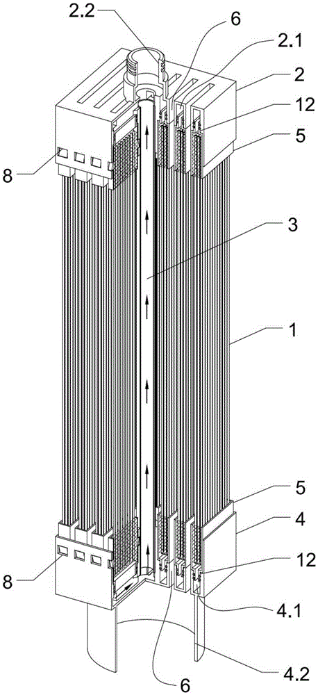
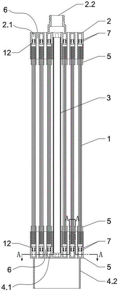
[0080] The head part is a housing with a collecting chamber. The end part divides the housing into an area with a through-channel and an area without a through-channel, wherein the through-channel completely penetrates the housing and becomes a drainage channel for the hollow fiber membrane tow row 1 . The casing surrounds the liquid collection chamber, which is a cavity. The liquid collecting chamber has multiple openings called the liquid collecting chamber receiving port, and the liquid collecting chamber receiving port is used to receive the connection of the liquid outlet of the hollow fiber membrane tow row 1, collect the output filtrate, and collect it into the liquid collecting chamber cavity. Both the liquid collecting chamber and the receiving port of the liquid collecting chamber are arranged on the area of ​​the housing without a through passage. Therefore, the through-channel and the liquid collection chamber are integrated in a housing such as the terminal part...

Embodiment 2

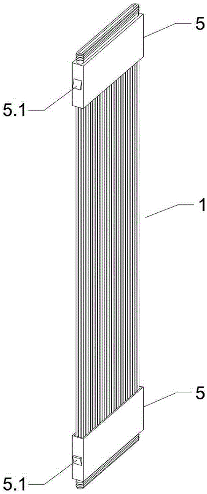
[0086] Such as figure 1 , figure 2 , image 3 As shown, the upper and lower ends of multiple hollow fiber membranes are cast and fixed in the filtrate collection plug 5 with resin and other materials to form a hollow fiber membrane tow row 1, and the hollow fiber membrane end faces in the filtrate collection plug 5 at the upper and lower ends are used for openings. After the filtered liquid flows out, a plurality of hollow fiber membrane tow rows 1 are arranged in parallel with each other between the upper end 2 and the lower end 4, and the filtrate collecting plugs 5 at the upper and lower ends of the hollow fiber membrane tow row 1 are arranged on both sides There are raised buckles 5.1, the two side walls of the corresponding positions of the upper end 2 and the lower end 4 are provided with buckle matching ports 8, and the raised buckles on both sides of the filtrate collection plug 5 at the upper and lower ends of the hollow fiber membrane tow row 1 The bit 5.1 is asse...

Embodiment 3

[0093] Such as Figure 8 As shown, a plurality of hollow fiber membrane module arrays form a membrane filtration unit, an aeration distribution pipe 101 and an aeration head 102 are arranged at the bottom of the hollow fiber membrane module, and a filtrate collection branch pipe 103 and a filtrate collection branch pipe 103 are arranged on the top. Manager 104. Among them such as Figure 9 , the aeration head 102 is located inside the fluid confinement cover 4.2 of the lower end 4 of the hollow fiber membrane module, and the aeration head 102 also plays a role of limiting and fixing the hollow fiber membrane module. The aeration distribution pipe 101 introduces gas from the gas source, releases it through the aeration head 102, and enters each hollow fiber membrane module.

[0094] Such as Figure 10 , the aerator head 102 is provided with an airflow buffer chamber 102.1, four airflow guide pipes 102.2 are radially distributed with the airflow buffer chamber 102.1 as the ce...


PUM


Abstract

The invention provides an end component of a hollow fiber membrane module. The end component is a shell provided with a liquid collection cavity; the end component comprises a through channel which penetrates through the shell completely and the liquid collection cavity. The invention further provides the hollow fiber membrane module. The hollow fiber membrane module comprises the end component, a hollow fiber membrane strand array, a support device and a main liquid collection pipeline; the end component comprises an upper end and a lower end which are located on the upper portion and the lower portion of the hollow fiber membrane module respectively; the upper end and the lower end of the hollow fiber membrane module each have a through groove structure. The end component and the hollow fiber membrane module have the function of outputting water both at the upper end and at the lower end simultaneously, the purpose of reducing pollution of the membrane module is achieved, and meanwhile, the filtering efficiency is improved through water output at the both ends; the hollow fiber membrane strand array is in a thin curtain shape as a whole, and the compact type integration design of the membrane module is achieved; the hollow fiber membrane strand array and the upper end and the lower end are of a detachable assembly structure, and the problem that the outer surface of a hollow fiber membrane at the root of the membrane module cannot be repaired is solved.

Description

technical field [0001] The invention relates to the field of water treatment, and more specifically relates to a terminal part, a hollow fiber membrane module and a membrane filtration unit. Background technique [0002] Membrane separation technology has been widely used in the fields of water purification or liquid filtration and separation. According to the structure of the membrane filtration system, it can be divided into shell pressurized membrane system and submerged membrane system. [0003] Among them, the submerged membrane system can treat the liquid to be filtered that contains high suspended solids, sludge and other pollutants. The membrane module in the submerged membrane system generally also has a liquid collection chamber for filtrate collection and an aeration structure for disturbing the membrane filaments to remove pollutants on the membrane filament surface. In the existing submerged membrane filtration system, the middle part of the membrane module usu...

Claims


Application Information

Patent Timeline
IPC IPC(8): B01D63/02B01D61/00C02F1/44
CPCB01D61/00B01D63/02C02F1/44
Inventor 陈忱陈良刚陈清吕鹏飞
Owner HAINAN LITREE PURIFYING TECH CO LTD
Why Eureka
Try Eureka