
A workbench device with rolling device for plate processing and using method thereof

A rolling device and plate processing technology, applied in the field of plate processing

Active Publication Date: 2017-10-17
PAGMAN TECH (TAICANG) CO LTD
View PDF8 Cites 0 Cited by
  • Summary
  • Abstract
  • Description
  • Claims
  • Application Information

AI Technical Summary

Problems solved by technology

However, it is difficult to meet this kind of processing characteristics and specific requirements in some existing workbench devices.

Method used


Image

  • A workbench device with rolling device for plate processing and using method thereof
  • A workbench device with rolling device for plate processing and using method thereof

Examples


Embodiment Construction

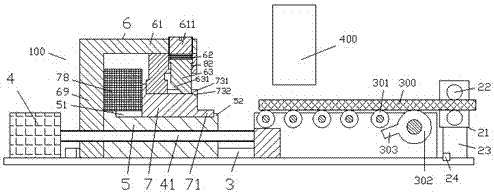
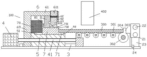
[0011] Combine below Figure 1-2 The present invention will be described in detail.

[0012] According to an embodiment, a workbench device with a rolling device for plate processing includes a transmission support device fixedly connected to the frame, a locking drive motor 4 fixedly connected to the frame, and a locking drive motor 4 4. A driving screw 41 coupled with power, and a locking assembly 100 driven by the thread on the driving screw 41, wherein the locking assembly 100 is used to approach the plate 300 under the drive of the locking driving motor 4 The side of the locking assembly 100 is positioned and locked; the conveying support device is located on the side of the locking assembly 100 and is provided with a plurality of rotatable conveying rollers 301 to support the plate 300 and facilitate the external thrust of the plate 300 To move towards the locking assembly 100 under action, the transmission support device is provided with a limit roller 302 driven by po...


PUM


Abstract

The invention provides a worktable device with a rolling device for sheet processing and an application method of the worktable device with a rolling device for sheet processing. The worktable device comprises a conveying supporting device fixedly connected with a frame, a locking driving motor (4) fixedly connected with the frame, a driving screw (41) in power connection with the locking driving motor (4), and a locking assembly (100) driven by threads on the driving screw (41), wherein the locking assembly (100) is used for positioning and locking a side portion, close to the locking assembly (100), of a sheet (300) under the driving of the locking driving motor (4); the conveying supporting device is located beside the locking assembly (100), and provided with a plurality of rotatable conveying rollers (301) to support the sheet (300) and facilitate the shifting of the sheet (300) toward the locking assembly (100) under the action of an external pushing force.

Description

technical field [0001] The invention relates to the field of sheet material processing, in particular to a workbench device with a rolling device for sheet material processing and a use method thereof. Background technique [0002] The plates need to be quickly loaded on the workbench to enter the processing position before processing. In order to ensure the processing quality, it is often necessary to position and lock the position of the plate. In fact, in some board processing procedures, such as painting, polishing or drying and drying, the external force caused by processing is small, so there is no need for a particularly strong fixing force to avoid trauma to the board. Moreover, the positioning process of these processes needs to be performed quickly and easily in the case of processing a large number of panels, so as to improve efficiency and reduce costs. However, it is difficult to meet the processing characteristics and specific requirements in some existing wo...

Claims


Application Information

Patent Timeline
Patent Type & Authority Patents(China)
IPC IPC(8): B25H1/00B25H1/10B21D1/02B23Q7/14B23Q7/05
CPCB21D1/02B23Q7/05B23Q7/1468B25H1/00B25H1/10
Inventor 付子勘
Owner PAGMAN TECH (TAICANG) CO LTD
Learn More