UAV high-energy ray transmitter equipped with gimbal

A technology of high-energy rays and transmitters, which is applied in the field of carrying gimbals, can solve problems such as the inability to mount other devices, and achieve the effect of improving operating efficiency and stability

Active Publication Date: 2017-07-07
STATE GRID CORP OF CHINA +1
View PDF6 Cites 0 Cited by
  • Summary
  • Abstract
  • Description
  • Claims
  • Application Information

AI Technical Summary

Problems solved by technology

[0002] The traditional multi-rotor UAV mount head is specially customized for the camera, and its mount and counterweight determine that other equipment cannot be mounted

Method used


Image

  • UAV high-energy ray transmitter equipped with gimbal
  • UAV high-energy ray transmitter equipped with gimbal
  • UAV high-energy ray transmitter equipped with gimbal

Examples


Embodiment Construction

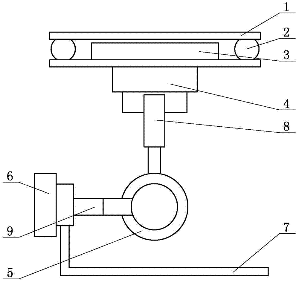
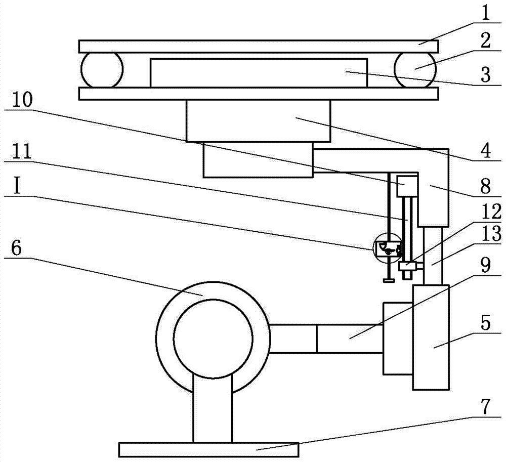
[0009] The UAV high-energy ray transmitter is equipped with a cloud platform, such as figure 1 and figure 2 As shown, it includes a pan-tilt connecting plate 1, a shock-absorbing ball 2 and a self-stabilizing controller 3 are installed in the middle of the pan-tilt connecting plate 1, and a direction shaft drive motor 4 is installed on the bottom of the pan-tilt connection plate 1, and the output of the direction shaft drive motor 4 A telescopic device is installed on the side of the shaft, one end of the telescopic device is connected to the direction shaft driving motor 4, the other end of the telescopic device is connected to the rolling shaft driving motor 5, the output shaft of the rolling shaft driving motor 5 is installed with a connecting rod 9, and one end of the connecting rod 9 is installed Pitch axis driving motor 6, the side of the output shaft of pitch axis driving motor 6 is equipped with mounting frame 7.

[0010] The invention is specially designed and produ...


PUM


Abstract

The invention discloses a carrying cloud deck for an unmanned aerial vehicle high-energy ray emitter. The carrying cloud deck comprises a cloud deck connecting plate. Damping balls and a self-stabilization controller are installed in the middle of the cloud deck connecting plate. A direction shaft driving motor is installed below the cloud deck connecting plate, a telescopic device is installed on the side portion of an output shaft of the direction shaft driving motor, and one end of the telescopic device is connected with the direction shaft driving motor. The carrying cloud deck is specially designed and manufactured for hanging the unmanned aerial vehicle high-energy ray emitter, the dimension and balance weight requirements are met, and the emitter can be carried to make rotation movement in three directions including the pitching direction, the rolling direction and the axial direction. The carrying cloud deck is carried with the self-stabilization controller, the posture of the cloud deck can be automatically corrected through combination of the posture of an unmanned aerial vehicle, and the hanging stability of the cloud deck is improved. The carrying cloud deck is mainly used for hanging the unmanned aerial vehicle high-energy ray emitter, the operations of removing guide lines and hanging foreign matter can be assisted to be completed, rotary control over the emitter can be realized, and the operation efficiency can be effectively improved.

Description

technical field [0001] The invention relates to a carrying platform, in particular to a carrying platform for a high-energy ray transmitter of an unmanned aerial vehicle. Background technique [0002] The traditional multi-rotor UAV mounting head is specially customized for the camera, and its mounting frame and counterweight determine that other equipment cannot be mounted. Contents of the invention [0003] The purpose of the present invention is to provide a UAV high-energy ray transmitter mounted platform, which can solve the above problems. [0004] In order to achieve the above object, the present invention is achieved through the following technical solutions: a high-energy ray transmitter for unmanned aerial vehicles is equipped with a cloud platform, including a cloud platform connecting plate, a shock absorbing ball and a self-stabilizing controller are installed in the middle of the cloud platform connecting plate, and the cloud platform The lower part of the c...

Claims


Application Information

Patent Timeline
Patent Type & Authority Patents(China)
IPC IPC(8): B64D47/08
CPCB64D47/08
Inventor 郑连勇李鲁张君张民孙阳王蔚蔡俊鹏毕斌李敏黄振宁卢志鹏袁森黄锐
Owner STATE GRID CORP OF CHINA
Why Eureka
Try Eureka