
Box type burner shaft kiln

A box-type and shaft kiln technology, used in lime production and other directions, can solve the problems of long calcination time, poor sealing, and uneven feeding and discharging of materials, so as to improve the phenomenon of uneven heat distribution, improve uniformity and sealing, The effect of reducing drag loss

Active Publication Date: 2016-02-17
ACRE COKING & REFRACTORY ENG CONSULTING CORP DALIAN MCC
View PDF6 Cites 4 Cited by
  • Summary
  • Abstract
  • Description
  • Claims
  • Application Information

AI Technical Summary

Problems solved by technology

When the problem of material burning and over-burning occurs, it can only be adjusted by controlling the ratio of the material and fuel added later. The adjustment effect can only appear after a long wait, and it needs to be repeated many times to achieve a good state. It takes longer to adjust, so it is time-consuming and labor-intensive
[0004] For fluid fuel shaft kilns, the fuel is generally fed into the kiln from the peripheral burners installed on the side wall of the calcination zone. Due to the influence of material resistance, gas flow and hot gas rising, the high-temperature gas cannot reach the center of the lower part of the calcination zone, resulting in Insufficient heat supply to this part results in underfiring. In order to compensate for this defect, the height of the calcination zone can only be increased.
The problems caused by this are that the kiln body is too high, resulting in large resistance loss, uneven heat distribution between the center and the surrounding area, and the calcination time of the material is too long, resulting in serious overcooking of the product.
In addition, the feeding and discharging equipment and exhaust device have uneven feeding and discharging, and the seal is not good, causing dust to fly, serious environmental pollution, and resulting in uneven product quality and high energy consumption

Method used


Image

  • Box type burner shaft kiln
  • Box type burner shaft kiln
  • Box type burner shaft kiln

Examples


Embodiment Construction

[0022] The specific embodiment of the present invention will be further described below in conjunction with accompanying drawing:

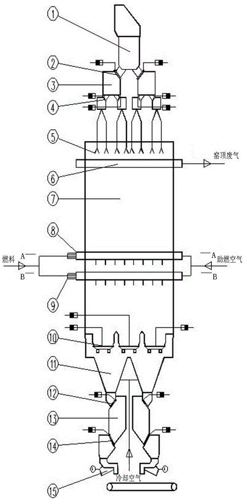
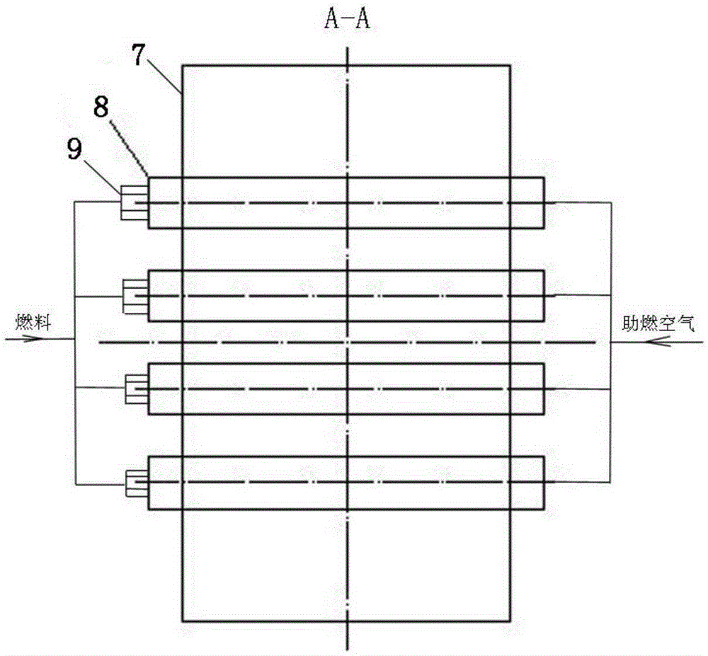
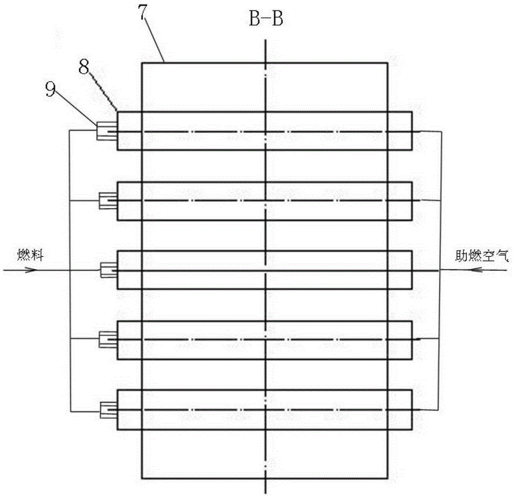
[0023] See figure 1 , is a structural representation of the present invention. The box-type burner vertical kiln of the present invention includes a kiln chamber 7, a kiln top exhaust device, a kiln top sealing feeding device and a kiln bottom sealing unloading device. The inside of the kiln chamber 7 is divided into preheating zone, calcining zone and cooling zone; the kiln chamber 7 at the lower part of the calcining zone is provided with at least two layers of box burners 8, and each layer of box burners 8 includes several burner boxes arranged in parallel horizontally, and the upper and lower two The layer burner boxes are arranged in a staggered manner; Figure 4 As shown, each burner box is provided with a plurality of fuel spray guns 9, and its fuel nozzles 17 are evenly arranged at the bottom of the burner box along the length direction;...


PUM


Abstract

The invention relates to a box type burner shaft kiln. The shaft kiln comprises a kiln chamber, a kiln top exhaust device, a kiln top seal feeding device and a kiln bottom seal discharging device. At least two layers of box type burners are arranged in the kiln chambers, each layer of box type burners comprises multiple burner boxes horizontally arrayed in parallel, the burner boxes in the upper layer and the burner boxes in the lower layer are arranged in a staggered mode, each burner box is internally provided with multiple fuel spray guns and communicated with an external combustion air conveying pipeline, and all the fuel spray guns and the combustion air conveying pipeline are each provided with an independent valve to be controlled. The fuel feed mode in the kiln chamber is optimized, fuel is evenly distributed on the cross section of the kiln chamber, the phenomenon of uneven heat distribution in the calcining process is improved, the height of the shaft kiln is reduced easily, and resistance loss in the kiln is reduced. The kiln body structure, the feeding and discharging modes and the exhaust mode are optimized at the same time, the evenness and seal performance of feeding and discharging are improved, the exhaust effect is improved, dust emission is reduced, and the purposes of improving product quality, saving energy and reducing emission are achieved.

Description

technical field [0001] The invention relates to a block material calcining kiln, in particular to a box-type burner shaft kiln. Background technique [0002] The general countercurrent calcining single-chamber shaft kiln, the calcination process in the kiln chamber is: the material moves from top to bottom, the high-temperature gas generated by fuel combustion flows from bottom to top, and the two countercurrent heat exchange achieves the purpose of calcining materials. [0003] The fuel of the solid fuel shaft kiln is generally fed into the kiln from the top of the kiln along with the calcined materials. It needs to be preheated by the preheating zone to burn and release heat in the calcination zone. This process takes about 20 hours. When the problem of material burning and overburning occurs, it can only be adjusted by controlling the ratio of the material and fuel added later. The adjustment effect will only appear after a long wait, and to achieve a good state, it needs...

Claims


Application Information

Patent Timeline
Patent Type & Authority Applications(China)
IPC IPC(8): C04B2/12
CPCY02P40/40
Inventor 程伟丰刘增赵宝海王洪涛杨耕桃
Owner ACRE COKING & REFRACTORY ENG CONSULTING CORP DALIAN MCC
Learn More