A washing machine deceleration clutch and washing machine

A deceleration clutch and washing machine technology, which is applied in the field of washing machines, can solve problems such as waste of space at the bottom, and achieve the effects of increasing washing capacity, reducing processing costs, and saving costs

Active Publication Date: 2019-07-02
QINGDAO HAIER WASHING MASCH CO LTD
View PDF2 Cites 0 Cited by
  • Summary
  • Abstract
  • Description
  • Claims
  • Application Information

AI Technical Summary

Problems solved by technology

[0005] Since the deceleration clutch of the washing machine is installed at the bottom of the outer tub / drum, and the diameter of the outer tub / drum is much larger than that of the deceleration clutch, there is still a large space around the deceleration clutch, and no other structures are installed in this part of the space, resulting in The bottom space is wasted, and the motor, deceleration device and clutch device of the deceleration clutch are arranged in sequence along the axial direction, which also causes a waste of bottom space. Therefore, how to reasonably arrange the clutch device, deceleration device and motor of the deceleration clutch to reduce The overall height of the deceleration clutch increases the washing capacity of the washing machine, which has become a technical problem that needs to be solved urgently

Method used


Image

  • A washing machine deceleration clutch and washing machine
  • A washing machine deceleration clutch and washing machine
  • A washing machine deceleration clutch and washing machine

Examples


Embodiment 1

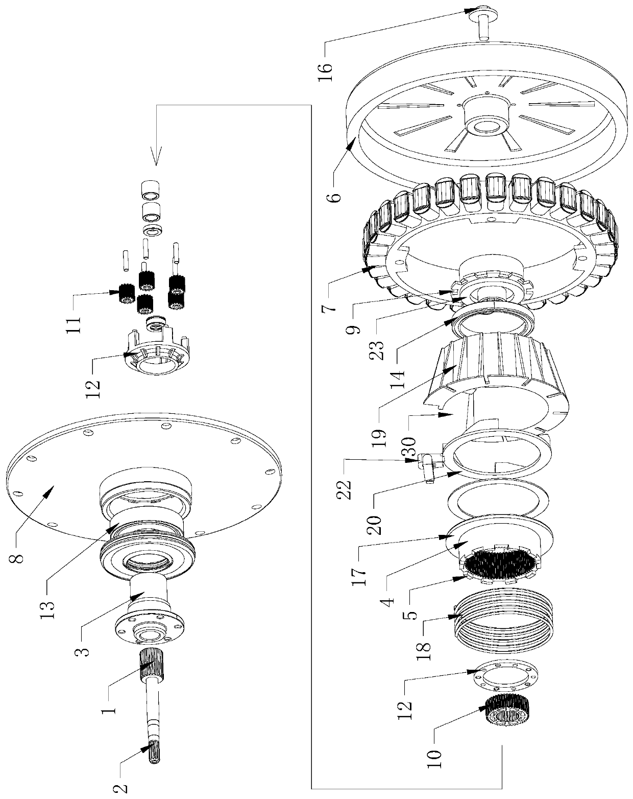
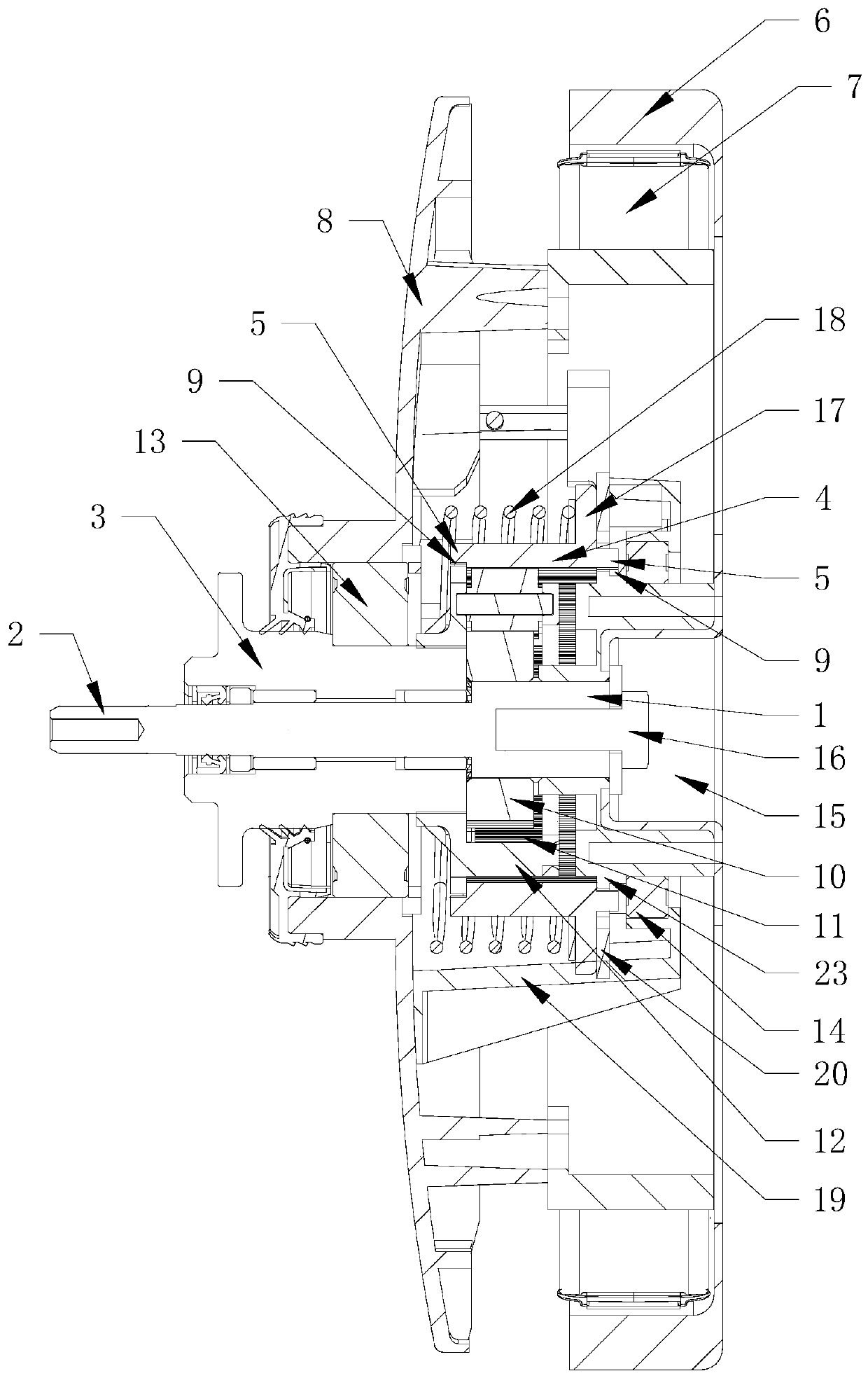
[0045] Such as figure 1 , figure 2 As shown, a washing machine deceleration clutch according to the present invention includes: an input shaft 1, a deceleration device, a clutch device, an output shaft 2 and an output shaft sleeve 3, and the clutch device is arranged on the circumferential periphery of the deceleration device, and the clutch The device at least includes an axially movable clutch bushing, the clutch bushing is the inner ring gear 4 of the reduction gear, the inner ring gear 4 moves axially and is connected with structures in different states, and controls the output shaft 2 and the output shaft sleeve 3 In different output states, the ring gear 4 meshes with at least some gears in the reduction gear.

[0046] If the above-mentioned washing machine is a vertical bucket pulsator washing machine, the output shaft 2 is connected to the pulsator, and the output bushing 3 is connected to the inner tub; if the above-mentioned washing machine is a drum pulsator washi...

Embodiment 2

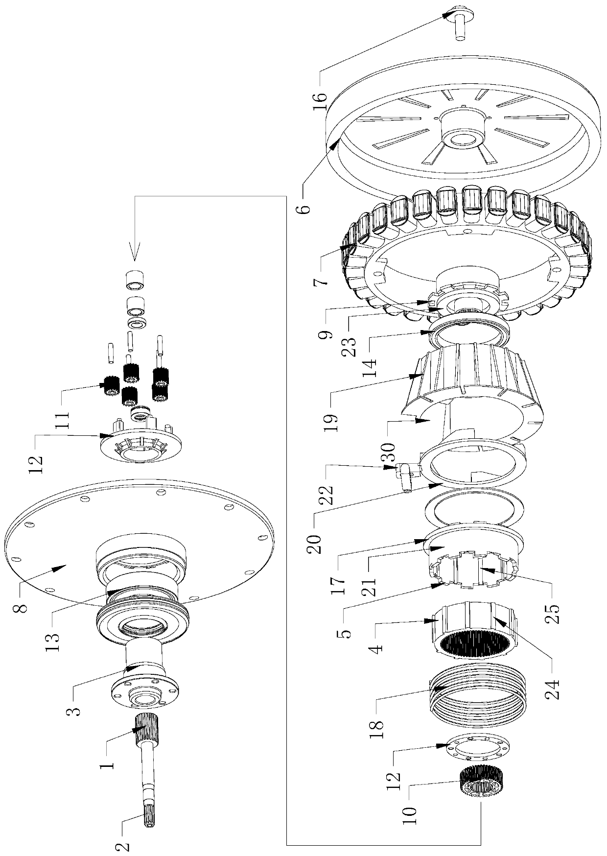
[0079] Such as image 3 , Figure 4 As shown, a washing machine deceleration clutch according to the present invention includes: an input shaft 1, a deceleration device, a clutch device, an output shaft 2 and an output shaft sleeve 3, and the clutch device is arranged on the circumferential periphery of the deceleration device, and the clutch The device at least includes a clutch sleeve 21 that can move axially, and the clutch sleeve 21 is arranged outside the ring gear 4 of the deceleration device, and is connected with the ring gear 4 in an axially relative sliding and circumferentially non-rotatable manner. The shaft sleeve 21 moves axially so that the ring gear 4 is connected to structures in different states through the clutch sleeve 21 to control the different output states of the output shaft 2 and the output sleeve 3. The ring gear 4 is connected to at least part of the reduction gear. gears meshing.

[0080] If the above-mentioned washing machine is a vertical bucke...

Embodiment 3

[0113] A washing machine having the deceleration clutch described in the first or second embodiment above, the washing machine is a pulsator washing machine or a drum washing machine.


PUM


Abstract

The invention relates to a washing machine deceleration clutch and a washing machine. The deceleration clutch comprises an input shaft, a deceleration device, a clutch device, an output shaft and an output shaft sleeve, wherein the clutch device is at least partially arranged on the periphery of the deceleration device; the clutch device at least comprises a clutch shaft sleeve capable of axially moving and a driving device driving the clutch shaft sleeve to axially move; the clutch shaft sleeve is arranged outside an annular gear of the deceleration device and is in a connection with the annular gear in way of being capable of sliding relative to the annular gear but incapable of rotating relative to the same; the driving device drives the clutch shaft sleeve to axially move to control different output states of the output shaft and the output shaft sleeve; the driving device comprises at least one clutch press plate coaxially arranged with the clutch shaft sleeve; and the clutch press plate can circumferentially rotate to drive the clutch shaft sleeve to axially move. The deceleration clutch is simply structured and axially occupies small space; and overall height of the deceleration height can be reduced and washing capacity can be increased.

Description

technical field [0001] The invention relates to the field of washing machines, in particular to a washing machine deceleration clutch and a washing machine with the deceleration clutch. Background technique [0002] Washing machines are household appliances commonly used in people's daily life. They are installed in different ways and can be divided into drum washing machines and pulsator washing machines. A drum washing machine generally includes an outer tub, a drum and a motor, and the motor drives the drum to rotate in the outer tub to wash or dehydrate the clothes. Present drum washing machines simply utilize the rotation of the drum for washing, and only use the lifting ribs in the drum to lift and drop the laundry to beat the clothes for washing, so it is difficult to obtain excellent washing effect. The current drum washing machine also has a pulsator in the drum, and the pulsator and the drum are respectively driven by independent motors to optimize the washing eff...

Claims


Application Information

Patent Timeline
Patent Type & Authority Patents(China)
IPC IPC(8): D06F37/30D06F37/40F16D48/00
Inventor 迟宗锐李全德栾厚利翟清明徐超王珊
Owner QINGDAO HAIER WASHING MASCH CO LTD
Why Eureka
Try Eureka