Rock and soil anchoring structure

An anchoring structure and geotechnical technology, which is applied in the direction of foundation structure engineering, building, sheet pile wall, etc., can solve the problems of limited friction and difficulty in meeting the requirements of design pullout force, so as to improve pullout force and enhance bonding The effect of friction

Inactive Publication Date: 2016-02-17
CHENGDU KECHUANG JIASI TECH
View PDF8 Cites 0 Cited by
  • Summary
  • Abstract
  • Description
  • Claims
  • Application Information

AI Technical Summary

Problems solved by technology

[0002] Rock-soil anchoring technology is an engineering technology that embeds a tensile member in the ground to improve the strength and self-stabilization ability of the rock and soil. Because this technology greatly reduces the self-weight of the structure, saves engineering materials, and ensures that the engineering Therefore, it is widely used in engineering. The rock and soil anchoring technology uses the shear strength of the rock and soil around the anchor to transmit the tensile force of the structure, or to maintain the excavation of the ground. The self-stability of the surface, it can provide the resistance to act on the structure to bear the external load, and can connect the structure and the formation together to form a complex that works together, so that it can effectively bear the tensile force and shear force, Anchor bolts in the prior art usually include an anchor head, a free section, and an anchor section. The bearing capacity of the anchor bolt mainly depends on the bond friction between the anchor piece, especially the anchor section, and the surrounding rock-soil medium. The section is only a straight line structure, often with limited friction, especially when the angle between the direction of force and the direction of the anchor is small, if the friction strength of the soil bond is low, it is often difficult to meet the design pullout force. requirements, therefore, there is a need for a geotechnical anchorage structure that can form bonded friction in multiple directions

Method used


Image

  • Rock and soil anchoring structure

Examples


Embodiment Construction

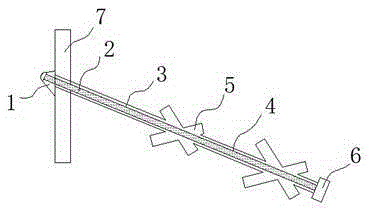
[0013] The present invention will now be described in further detail in conjunction with the accompanying drawings, which are simplified schematic diagrams, only schematically illustrating the basic structure of the present invention, and therefore only show the configurations related to the present invention.

[0014] like figure 1 The preferred embodiment of the rock-soil anchoring structure of the present invention shown includes an anchor head 1, an anchor rod body 2, a free section 3, an anchor section 4 and an auxiliary anchor section 5, and the anchor head 1 is fixed on the retaining structure 7 and Connect one end of the anchor body 2, the other end of the anchor body 2 extends into the rock and soil to form a free section 3 and an anchor section 4, the auxiliary anchor section 5 intersects with the anchor section 4, and the anchor section 4 and the auxiliary section The inside of the anchoring section 5 is a grouting body connected as a whole, the auxiliary anchoring ...


PUM


Abstract

The invention discloses a rock and soil anchoring structure. The rock and soil anchoring structure comprises an anchor head, an anchor rod body, a free section, an anchoring section and auxiliary anchoring sections. The anchor head is fixed to a retaining structure and connected with one end of the anchor rod body. The other end of the anchor rod body stretches into rock and soil to form the free section and the anchoring section. The auxiliary anchoring sections and the anchoring section intersect. A grouting body connected into a whole is arranged in the anchoring section and the auxiliary anchoring sections. By means of the rock and soil anchoring structure, the auxiliary anchoring sections and the anchoring section intersect, the grouting body connected into the whole is arranged in the anchoring section and the auxiliary anchoring sections, a linear structure of an anchor rod in the prior art is changed, adhesive friction force can be formed in multiple directions, the adhesive friction force between the anchoring section and a surrounding rock and soil medium is enhanced, and the pulling resistance of the rock and soil anchoring device is improved.

Description

technical field [0001] The invention relates to a civil construction facility, in particular to a rock-soil anchoring structure. Background technique [0002] Rock-soil anchoring technology is an engineering technology that embeds a tensile member in the ground to improve the strength and self-stabilization ability of the rock and soil. Because this technology greatly reduces the self-weight of the structure, saves engineering materials, and ensures that the engineering Therefore, it is widely used in engineering. The rock and soil anchoring technology uses the shear strength of the rock and soil around the anchor to transmit the tensile force of the structure, or to maintain the excavation of the ground. The self-stability of the surface, it can provide the resistance to act on the structure to bear the external load, and can connect the structure and the formation together to form a complex that works together, so that it can effectively bear the tensile force and shear fo...

Claims


Application Information

Patent Timeline
Patent Type & Authority Applications(China)
IPC IPC(8): E02D5/76
Inventor 缪家戌
Owner CHENGDU KECHUANG JIASI TECH
Why Eureka
Try Eureka