Field calibration device for hydraulic displacement servo system

A technology of servo system and on-site calibration, which is applied in the field of geometric quantity measurement, can solve problems such as the inability to calibrate the hydraulic displacement servo system, achieve the effects of eliminating disturbance effects, eliminating Abbe errors, and improving calibration accuracy

Active Publication Date: 2016-02-17
BEIJING CHANGCHENG INST OF METROLOGY & MEASUREMENT AVIATION IND CORP OF CHINA
View PDF6 Cites 2 Cited by
  • Summary
  • Abstract
  • Description
  • Claims
  • Application Information

AI Technical Summary

Problems solved by technology

[0004] The purpose of the present invention is to solve the current problem that the hydraulic displacement servo system cannot be calibrated on-site and realize the traceability of the on-site displacement, and proposes an on-site calibration device for the hydraulic displacement servo system, which can realize on-site calibration and traceability of the on-site displacement

Method used


Image

  • Field calibration device for hydraulic displacement servo system
  • Field calibration device for hydraulic displacement servo system
  • Field calibration device for hydraulic displacement servo system

Examples


Embodiment 1

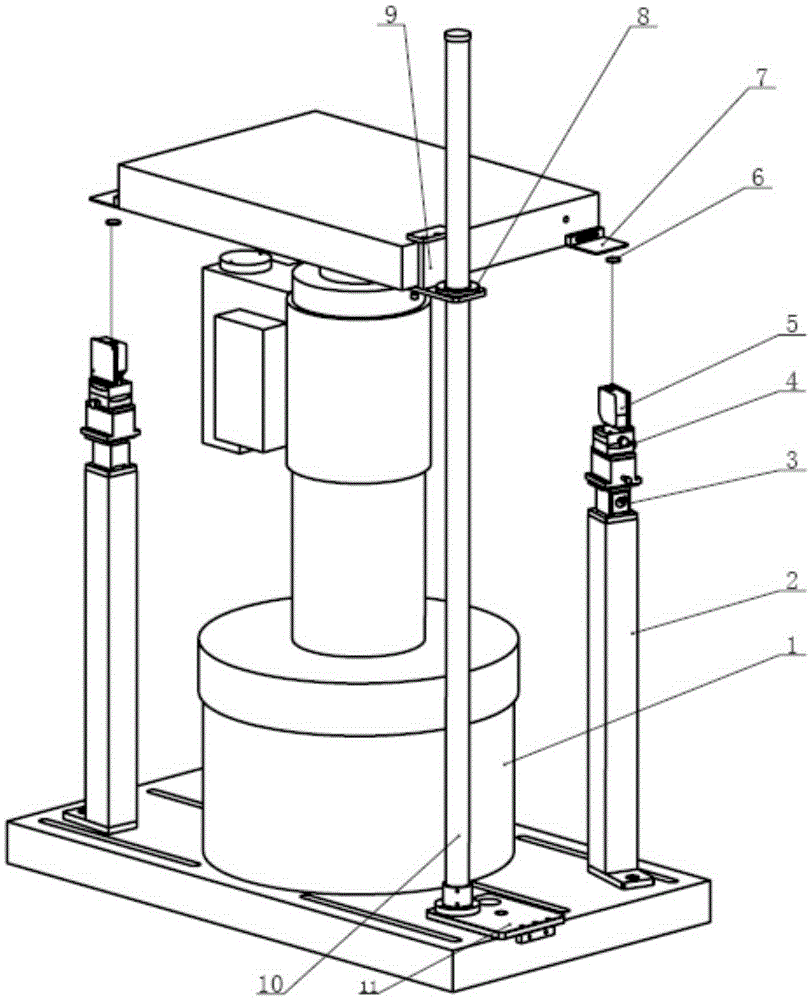
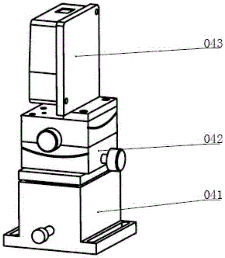
[0026] like figure 1 , figure 2 , image 3 , Figure 4 As shown, an on-site calibration device for a hydraulic displacement servo system includes a two-way laser displacement sensor 5, a sensor posture adjustment mechanism 4, a column 2, a laser reflector 7, a magnetic target 6 and a guide mechanism.

[0027] The two uprights 2 are fixedly installed at the diagonal position of the hydraulic cylinder base, using screw fixation or making the bottom of the uprights 2 large enough and heavy enough to place the sensor posture adjustment mechanism stably, placing it directly on the hydraulic cylinder base. Yes, in order to make the device of the present invention more versatile, this embodiment adopts the latter. The column can be made of aluminum profiles, cast iron, steel and other materials, and the cross-sectional shape can adopt stable shapes such as round or square. In addition, in order to facilitate installation and disassembly, the sensor posture adjustment mechanism 4...


PUM


Abstract

The invention relates to a field calibration device for a hydraulic displacement servo system and belongs to the technical field of geometrical measurement. The field calibration device comprises two ways of laser displacement sensors (5), sensor pose adjustment mechanisms (4), stand columns (2), laser reflecting plates (7) and magnetic targets (6) and a working table guiding mechanism, wherein the two stand columns are symmetrically disposed on a hydraulic cylinder base; the sensor pose adjustment mechanisms are mounted on the stand columns through magnetic force; the laser displacement sensors are fixedly mounted on the sensor pose adjustment mechanisms; the laser reflecting plates are disposed on a hydraulic displacement servo system working table; the magnetic targets are attracted to the laser reflecting plates through magnetic force; the working table guiding mechanism is fixedly mounted on the hydraulic cylinder base. Field calibration for the hydraulic displacement servo system can be performed; displacement tracing is achieved; the two ways of laser displacement sensors are symmetrically disposed, so that Abbe errors due to the fact the laser displacement sensors cannot be mounted in the center of a moving axis are effectively eliminated, and the calibration accuracy is improved.

Description

technical field [0001] The invention relates to a field calibration device, in particular to a field calibration device of a hydraulic displacement servo system, and belongs to the technical field of geometric measurement. Background technique [0002] The hydraulic displacement servo system can be used as a vertical motion excitation system to provide a simulated vehicle motion environment, and to study the influence of vibration on vehicle comfort, dynamic load of each system, and the strength and life of parts when the vehicle is running. The complete vehicle, related systems, and assembly components of heavy and off-road vehicles are subjected to simulation tests and routine tests in road and vibration environments. [0003] Hydraulic displacement servo system is a comprehensive test system composed of single or multiple sets of hydraulic cylinders with fixed installation and complex structure. When the servo system is working, the worktable is in a suspended state, and ...

Claims


Application Information

Patent Timeline
IPC IPC(8): F15B19/00
Inventor 何小妹王爱军唐志锋李昆王一璋
Owner BEIJING CHANGCHENG INST OF METROLOGY & MEASUREMENT AVIATION IND CORP OF CHINA
Why Eureka
Try Eureka