Hydraulic oil cooling structure

A technology of cooling structure and hydraulic oil, which is applied in the direction of fluid pressure actuating device, fluid pressure actuating system components, mechanical equipment, etc., and can solve the problems of high-speed, frequent failure of hydraulic equipment, unstable operation of hydraulic equipment, etc.

Inactive Publication Date: 2016-02-17
四川海搏液压机械有限公司
View PDF5 Cites 2 Cited by
  • Summary
  • Abstract
  • Description
  • Claims
  • Application Information

AI Technical Summary

Problems solved by technology

[0003] At present, the hydraulic oil used in hydraulic equipment mainly relies on natural cooling, and the cooling effect is relatively poor. Due to the increase in the temperature of the hydraulic oil, the hydraulic equipment fails frequently, which increases the failure rate and causes the hydraulic equipment to work unstable.

Method used


Image

  • Hydraulic oil cooling structure
  • Hydraulic oil cooling structure

Examples


Embodiment 1

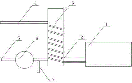
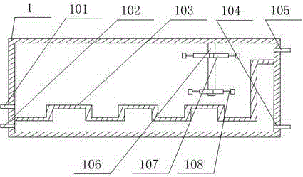
[0021] Such as figure 1 and figure 2 As shown, this embodiment includes a water tank 1 and a heat exchange cylinder 3, the upper and lower ends of the heat exchange cylinder 3 are respectively connected with a liquid outlet pipe 5 and a liquid return pipe 4, and a cooling pipe is respectively opened on the lower section of the side wall at one end of the water tank 1. Liquid outlet 101, hot liquid inlet 102, the upper section of the side wall at the other end of the water tank 1 has a cold liquid inlet 105 and its lower section has a hot liquid outlet 104, and the cold liquid outlet 101 communicates with the hot liquid inlet 102 through the heat exchange tube 2, And the heat exchange tube 2 is spirally wound on the outer peripheral wall of the heat exchange tube 3 along the axial direction, and a corrugated plate 103 is installed in the box to divide it into two parts, and the corrugated plate 103 is far away from the cooling liquid outlet One end of 101 is bent and then ext...


PUM


Abstract

The invention discloses a hydraulic oil cooling structure. The hydraulic oil cooling structure comprises a water tank and a heat exchange cylinder; the upper and lower ends of the heat exchange cylinder are connected with a liquid outlet pipe and a liquid return pipe, respectively; a cold liquid outlet and a hot liquid inlet are formed in lower sections of sidewalls of one end of the water tank, respectively; a cold liquid inlet is formed in an upper section of a sidewall of the other end of the water tank and a hot liquid outlet is formed in a lower section thereof; the cold liquid outlet communicates with the hot liquid inlet through a heat exchange tube; the heat exchange tube is spirally wound on an outer peripheral wall of the heat exchange cylinder in an axis direction of the heat exchange cylinder; a corrugated board is mounted within the tank body to divide the water tank into two parts; the end portion of one end, far away from the cold liquid outlet, is bent to extend upwards to be connected with an inner wall of the tank body close to the cold liquid inlet. Hydraulic oil at a high temperature flows into the heat exchange cylinder from the liquid outlet pipe; a purpose of cooling the hydraulic oil is achieved through heat exchange between the heat exchange cylinder and the heat exchange tube, and then the cooled hydraulic oil returns to a hydraulic system from the liquid return pipe to be reused.

Description

technical field [0001] The invention relates to cooling equipment, in particular to a hydraulic oil cooling structure. Background technique [0002] Hydraulic equipment refers to the device that transmits pressure through hydraulic oil and is the carrier of the hydraulic system. A complete hydraulic system consists of five parts, namely power components, actuators, control components, auxiliary components and hydraulic oil. The function of hydraulic cylinder and hydraulic motor, the actuators of the hydraulic system, is to convert the pressure energy of the liquid into mechanical energy to obtain the required linear reciprocating motion or rotary motion. Hydraulic equipment has the characteristics of large transmission force, easy transmission and configuration, so it is widely used in industrial and civil industries. [0003] At present, the hydraulic oil used in hydraulic equipment mainly relies on natural cooling, and the cooling effect is relatively poor. Due to the in...

Claims


Application Information

Patent Timeline
Patent Type & Authority Applications(China)
IPC IPC(8): F15B21/04
CPCF15B21/042
Inventor 谭继威邓国强
Owner 四川海搏液压机械有限公司
Why Eureka
Try Eureka