Boiler tail gas waste heat recovery device and recovery method based on split-flow heating technology

A technology for waste heat recovery equipment and boilers, applied in lighting and heating equipment, heat exchange equipment, heat exchangers, etc., can solve problems such as heat pollution, energy waste, and environmental impact

Pending Publication Date: 2021-05-18
何建华
View PDF7 Cites 1 Cited by
  • Summary
  • Abstract
  • Description
  • Claims
  • Application Information

AI Technical Summary

Problems solved by technology

[0003] Boiler exhaust gas usually contains a large amount of heat, which is usually discharged directly with the exhaust gas. This discharge not only causes energy waste, but also causes thermal pollution, which has a profound impact on the environment.

Method used


Image

  • Boiler tail gas waste heat recovery device and recovery method based on split-flow heating technology
  • Boiler tail gas waste heat recovery device and recovery method based on split-flow heating technology
  • Boiler tail gas waste heat recovery device and recovery method based on split-flow heating technology

Examples


Embodiment 1

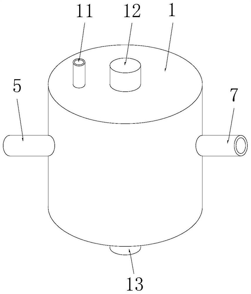
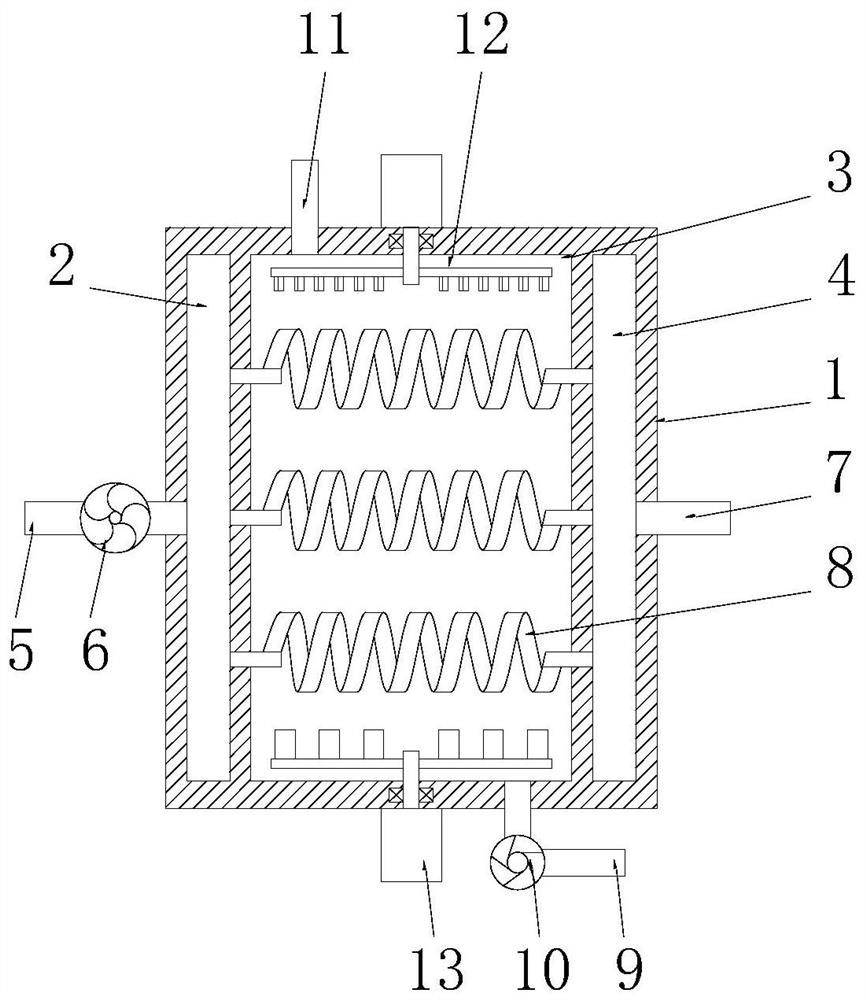
[0032] See Figure 1-2 , a boiler tail gas waste heat recovery device based on split heating technology, comprising an exchange box 1, the exchange box 1 is a cylindrical structure, the exchange box 1 is provided with an air intake chamber 2, a heat exchange chamber 3 and an air outlet chamber 4, The heat exchange chamber 3 is located in the middle of the exchange box 1, the air inlet chamber 2 and the air outlet chamber 4 have the same structure, the air inlet chamber 2 and the air outlet chamber 4 are arc-shaped chambers, and the air inlet chamber 2 and the air outlet chamber 4 are symmetrically arranged on the left and right sides of the heat exchange chamber 3, one end of the air inlet chamber 2 is connected to the inlet pipe 5, and the air intake pump 6 is installed on the inlet pipe 5, and one end of the air outlet chamber 4 is connected to the outlet pipe. Air pipe 7, a number of heat exchange tubes 8 are evenly arranged in the heat exchange chamber 3, the heat exchange...

Embodiment 2

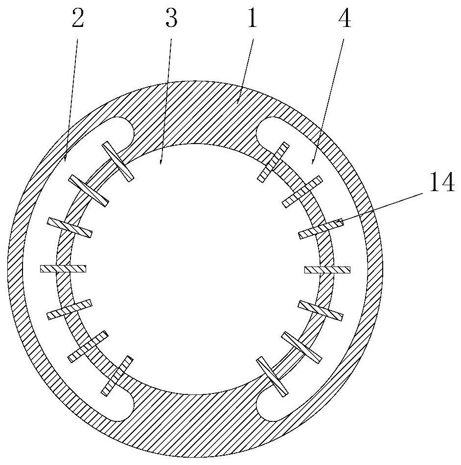
[0036] See Figure 3-4 The difference from Example 1 is that: the side wall of the heat exchange chamber 3 is evenly embedded with a number of heat exchange fins 14 that match the air outlet chamber 4, and the heat exchange fins 14 include two substrates 141 , the substrate 141 is a corrugated structure, the substrate 141 is made of aluminum alloy material, and a plurality of second connecting plates 143 and a plurality of first connecting plates 142 are arranged between the two substrates 141, all of the The second connection plates 143 are arranged side by side in parallel, all the first connection plates 142 are arranged in parallel, the relationship between the first connection plates 142 and the second connection plates 143 is perpendicular to each other, and the heat exchange fins 14 are The heat exchange chamber 3 and the air inlet chamber 2 or the air outlet chamber 4 are connected by two substrates 141, and then the waste heat in the auxiliary boiler exhaust gas and t...

Embodiment 3

[0038] See Figure 5-6 The difference from Embodiment 1 is that the first stirring mechanism 12 includes a first motor 121 and a first stirring shaft 122, the first motor 121 is fixedly connected to the top of the exchange box 1, and the first stirring shaft 122 is located in the heat exchange chamber 3, the axis of the first stirring shaft 122 coincides with the axis of the heat exchange chamber 3, the top of the first stirring shaft 122 penetrates the top wall of the heat exchange chamber 3 and is rotatably connected to the first motor 121, The first stirring shaft 122 is rotatably connected to the exchange box 1 through the first bearing 123, and the outer circular surface of the first stirring shaft 122 is evenly provided with a plurality of first stirring plates 124, and the bottom ends of the first stirring plates 124 are evenly arranged. It is provided with several first stirring blades 125, and the first stirring blades 125 are arranged obliquely, and the side ends of ...


PUM


Abstract

The invention discloses a boiler tail gas waste heat recovery device and recovery method based on the split-flow heating technology. The device comprises an exchange box, a gas-inlet cavity, a heat exchange cavity and a gas-outlet cavity are formed in the exchange box, one end of the gas-inlet cavity is connected with a gas-inlet pipe in a penetrating mode, a gas suction pump is mounted on the gas-inlet pipe, one end of the gas-outlet cavity is connected with a gas-outlet pipe in a penetrating mode, a plurality of heat exchange pipes are uniformly arranged in the heat exchange cavity, one ends of the heat exchange pipes are connected with the gas-inlet cavity in a communicating manner, and the other ends of the heat exchange pipes are connected with the gas-outlet cavity in a communicating manner. In the whole boiler tail gas heat exchange process, the filtered boiler tail gas exchanges heat with water in the heat exchange cavity through the heat exchange pipes, and then the boiler tail gas can be adopted to preheat and heat the water in the heat exchange cavity so that cooling treatment of the boiler tail gas is achieved, heat pollution is prevented, secondary utilization of waste heat in the tail gas of the boiler is achieved, the heat utilization efficiency of the boiler can be greatly improved, the energy utilization rate can be greatly increased, and the energy consumption can be reduced.

Description

technical field [0001] The invention relates to the technical field of boiler tail gas waste heat recovery, in particular to a boiler tail gas waste heat recovery device and recovery method based on split heating technology. Background technique [0002] The boiler is a kind of energy conversion equipment. The energy input to the boiler includes chemical energy and electric energy in the fuel, and the boiler outputs steam, high-temperature water or organic heat carrier with a certain amount of heat energy. The original meaning of the pot refers to the water container heated on the fire, and the furnace refers to the place where fuel is burned. The boiler includes two parts: the pot and the furnace. The hot water or steam generated in the boiler can directly provide the required heat energy for industrial production and people's life, and can also be converted into mechanical energy through a steam power device, or converted into electrical energy through a generator. [000...

Claims


Application Information

Patent Timeline
Patent Type & Authority Applications(China)
IPC IPC(8): F28D7/02F28D21/00F28F13/12
CPCF28D7/02F28D21/0003F28F13/125
Inventor 何建华
Owner 何建华
Why Eureka
Try Eureka