Rotation type reflow soldering furnace and soldering method thereof

A reflow soldering furnace and rotary technology, applied in the direction of welding equipment, electric heating devices, auxiliary devices, etc., can solve the problems of affecting the heating and cooling temperature field, energy loss, and mutual influence of hot and cold air, so as to improve heat utilization efficiency, Save welding time and wide application range

Inactive Publication Date: 2013-10-23
WUHAN FINEMEMS
View PDF0 Cites 15 Cited by
  • Summary
  • Abstract
  • Description
  • Claims
  • Application Information

AI Technical Summary

Problems solved by technology

But the heating zone and the cooling zone are connected, and the hot and cold air will interact or mix, which will have an adverse effect on the originally desired hot or cold environment.
This also affects the heating and cooling temperature field and causes a certain energy loss
[0004] Therefore, for the current vacuum reflow soldering furnaces with existing structures, since most of them use radiation for heat transfer, their convective heat transfer is not strong or there is no convective heat transfer, and there are disadvantages of slow heat transfer and low efficiency of radiation heating.
Moreover, these structures are difficult to reflow soldering in vacuum or protective atmosphere, because the loading and unloading of the welded parts in the assembly line welding cannot ensure that the welding equipment forms a vacuum environment and a protective atmosphere environment.

Method used


Image

  • Rotation type reflow soldering furnace and soldering method thereof
  • Rotation type reflow soldering furnace and soldering method thereof
  • Rotation type reflow soldering furnace and soldering method thereof

Examples


Embodiment Construction

[0025] Further illustrate this embodiment below in conjunction with accompanying drawing:

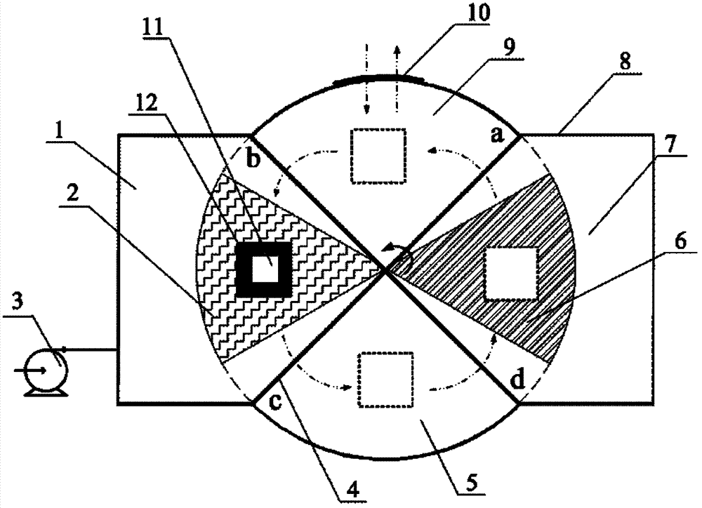
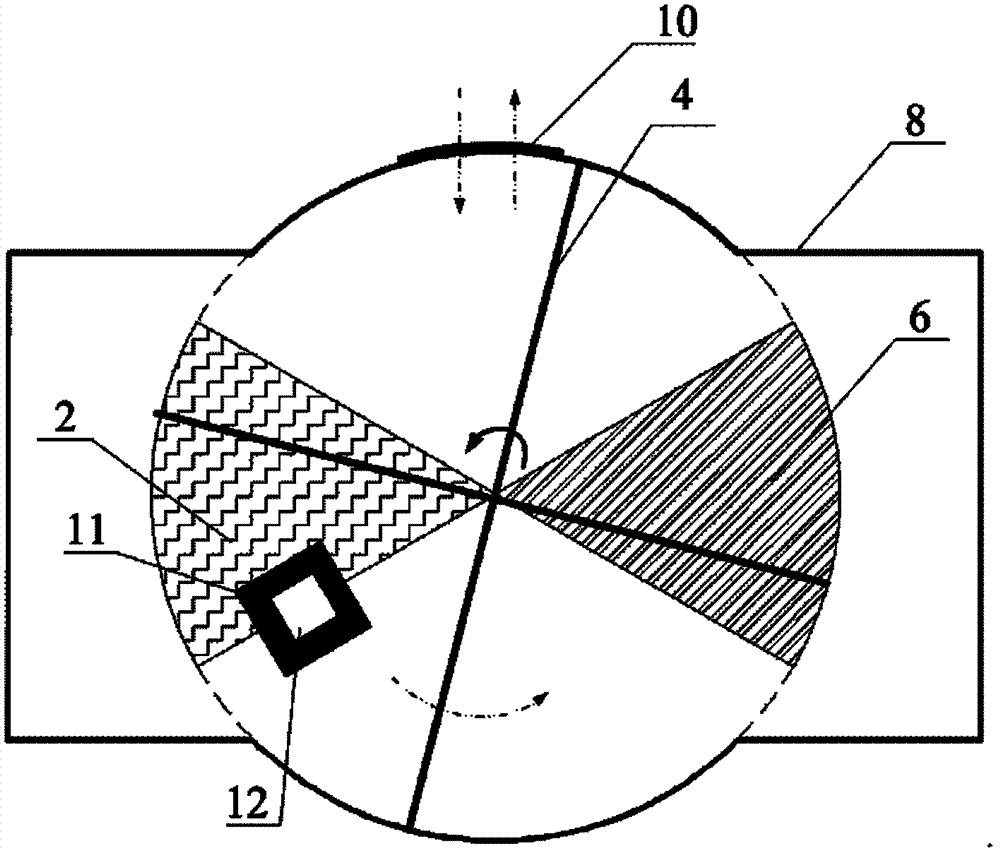
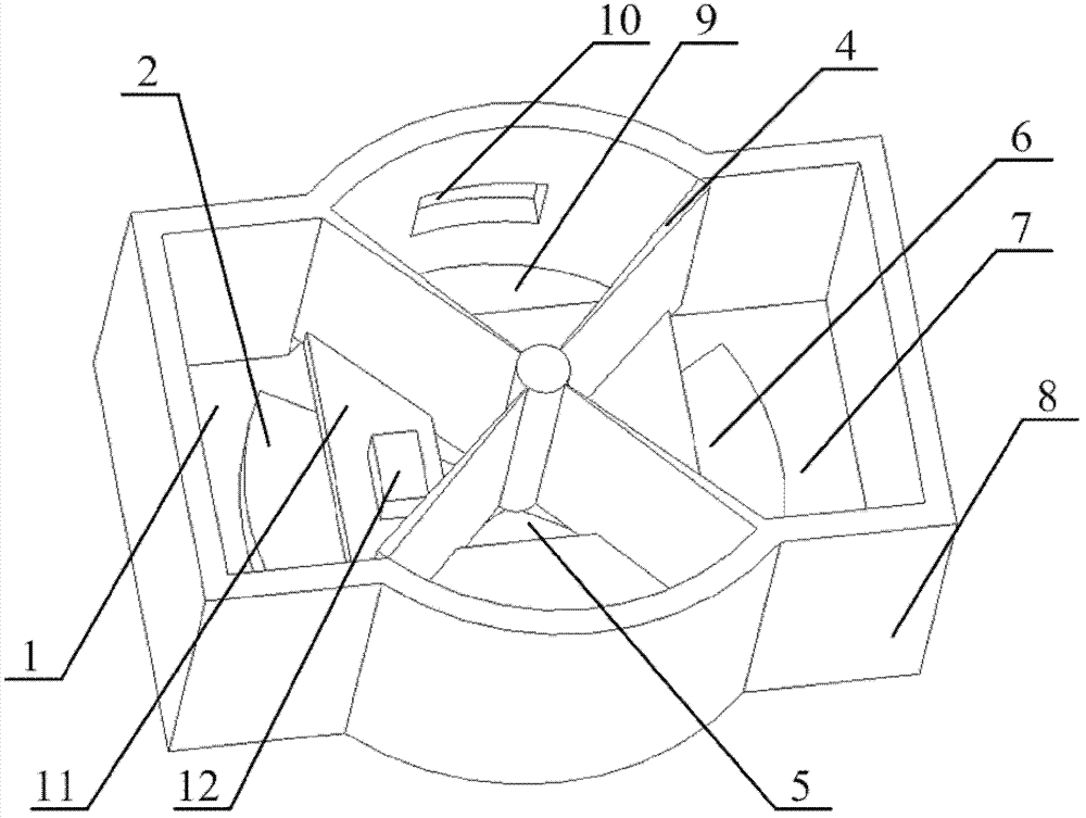
[0026] figure 1 is a plan view of the main functional components of the rotary reflow soldering furnace according to the present embodiment, such as figure 1 As shown in , the present invention consists of hot plate 2, cold plate 6, impeller 4, tray 11, vacuum pump 3, furnace door 10, furnace body 8, object to be welded 12, temperature controller 14, rotation control device 15, tray position adjustment Device 16 etc. are formed. The material of the impeller 4 is made of rigid thermal insulation material, such as aluminum silicate ceramic material, which has better thermal insulation performance. The circular area at the bottom of the impeller 4 is divided into four fan-shaped areas with the same area and size with a fan-shaped angle of 90 degrees. And the blade of impeller 4 is vertically projected on the leaf length line segment of furnace bottom plane and the four dividing lines of...


PUM


Abstract

A rotation type reflow soldering furnace comprises a furnace body, a furnace door, an impeller, a rotation control device, a tray, a tray position adjusting device, a vacuum pump and a temperature controller. The rotation type reflow soldering furnace is characterized in that the furnace body is formed by intersection of a cylinder and a cuboid equal in height, the furnace door is arranged on the wall of the furnace body, the furnace body is divided into a loading zone, a heating zone, a buffering zone and a cooling zone, a hot plate is arranged in the heating zone, a cold plate is arranged in the cooling zone, the impeller is arranged in the furnace body and connected with the rotation control device in a circuit manner, a to-be-soldered electronic component and a solder tray are placed between two blades, a vacuum pipe is connected with the heating zone via a pipeline, and the temperature controller is connected with the hot plate and the cold plate via circuits. The rotation type reflow soldering furnace has the advantages that the rotation type reflow soldering furnace has an independent heating system and an independent cooling system, and can perform non-interfering heating and cooling processes in a vacuum or protective atmosphere, repeated heating and cooling is not needed, and accordingly soldering time can be saved, power consumption is reduced, and working efficiency and soldering quality are improved.

Description

technical field [0001] The invention relates to a welding equipment and method, in particular to a reflow welding furnace and a welding method thereof. Background technique [0002] As electronic component packages shrink in size and power levels increase, the need for void-free soldering arises. Since soldering in a low-oxygen or oxygen-free environment can reduce the generation of voids in the soldering process and improve the quality of welding, it is accordingly desirable to enable the reflow soldering process to be performed in a low-oxygen or oxygen-free environment. However, most of the current reflow soldering furnaces are soldered in an atmospheric environment, the generation of voids cannot be controlled, and the soldering quality is not high. [0003] In addition, for the small reflow soldering furnaces in the prior art, the whole process of reflow soldering is generally realized in one cavity space. Each soldering job needs to be heated from room temperature to...

Claims


Application Information

Patent Timeline
Patent Type & Authority Applications(China)
IPC IPC(8): B23K3/00B23K3/047B23K3/08B23K1/008
Inventor 刘胜桂许龙罗小兵周洋陈明祥
Owner WUHAN FINEMEMS
Why Eureka
Try Eureka