
Electric cookware with efficient heat dissipation function

A cooking utensil and high-efficiency technology are applied in the field of high-efficiency heat dissipation electric cooking utensils, which can solve the problems of increasing food cooking time, affecting food taste, heat waste, etc., and achieving the effects of improving heat utilization efficiency, improving texture and taste, and reducing time.

Pending Publication Date: 2018-11-09
FOSHAN SHUNDE KUFU ELECTRIC APPLIANCES CO LTD
View PDF6 Cites 15 Cited by
  • Summary
  • Abstract
  • Description
  • Claims
  • Application Information

AI Technical Summary

Problems solved by technology

In the above technical solution, the cold wind wheel is arranged above the motor, specifically between the motor and the air inlet hole, and the cold wind introduced by the wind-inducing wind wheel from the outside of the casing mainly acts between the casing and the food cavity, and transfers the food cavity to the food cavity. The heat from the casing part is driven downwards and discharged through the air outlet at the bottom. The disadvantage of this arrangement is that the cold wind introduced into the casing by the cold wind wheel does not directly act on the motor, and the heat generated by the motor is accumulated, resulting in The temperature of the motor itself is too high, which in turn will damage the motor; moreover, the cold wind directly acts on the outer wall of the cavity, generating cold wind with a relatively large flow rate on the outer wall, and the heat transferred from the cavity to the outer wall is directly discharged by the cold wind. The problem of residual harmful heat, but it will take away more useful heat. The temperature difference between the inside and outside of the cavity is too high, causing part of the useful heat to be directly transferred to the outer wall of the cavity, and then taken out, resulting in waste of heat, which in turn increases food consumption. Cooking time, as the cooking time increases, it will affect the taste of food, especially for foods such as French fries, long-term heating will lead to softness and poor texture

Method used


Image

  • Electric cookware with efficient heat dissipation function
  • Electric cookware with efficient heat dissipation function
  • Electric cookware with efficient heat dissipation function

Examples


Embodiment 1

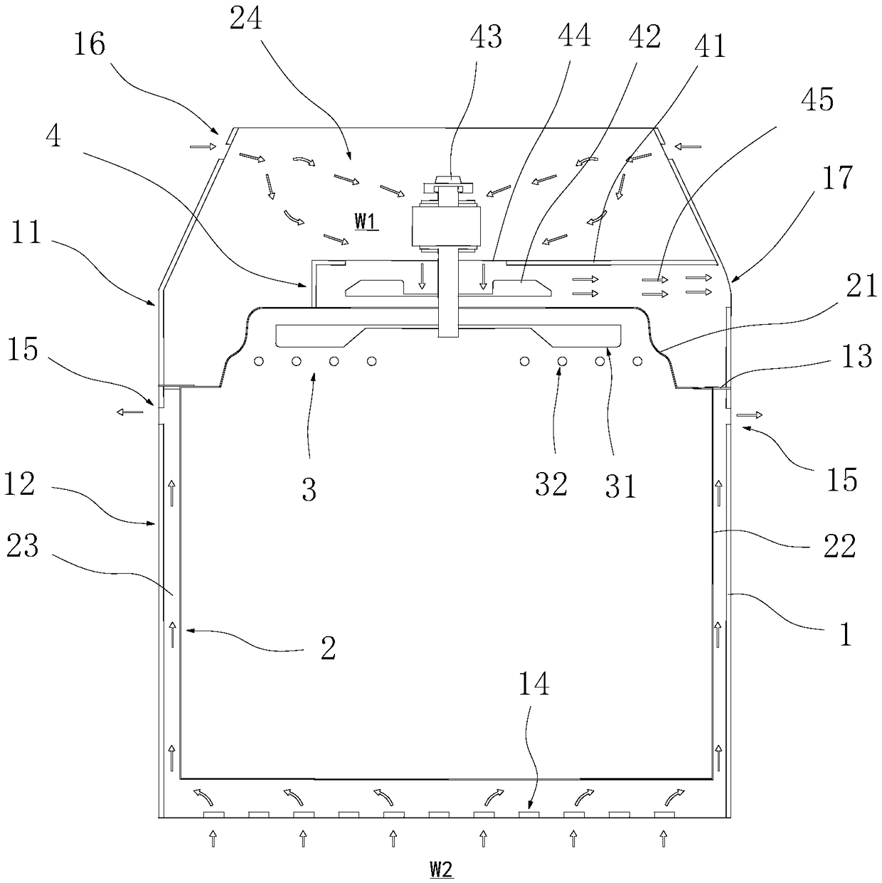
[0048] This embodiment provides a high-efficiency heat dissipation electric cooking appliance, such as figure 1 As shown, it includes a housing 1, a food preparation chamber 2, a heating device 3 and an air induction device 4.

[0049] Wherein, the shell 1 includes an upper shell 11, a lower shell 12 and a liner 13 arranged between the upper shell 11 and the lower shell 12, wherein the liner 13 connects the upper shell 11 and the lower shell 12 The space is isolated, and the gas between the upper casing 11 and the lower casing 12 is close to or not exchanged or circulated at all.

[0050] The food preparation chamber 2 is located at the inside of the lower casing 12, and the top of the food preparation chamber 2 is covered with a blast hood 21, and the heating device 3 is located in the blast hood 21, and the heating device 3 includes a blast wind wheel 31 and an electric heater. The tube 32, the electric heating tube 32 is arranged directly below the blast wheel 31, the blas...

Embodiment 2

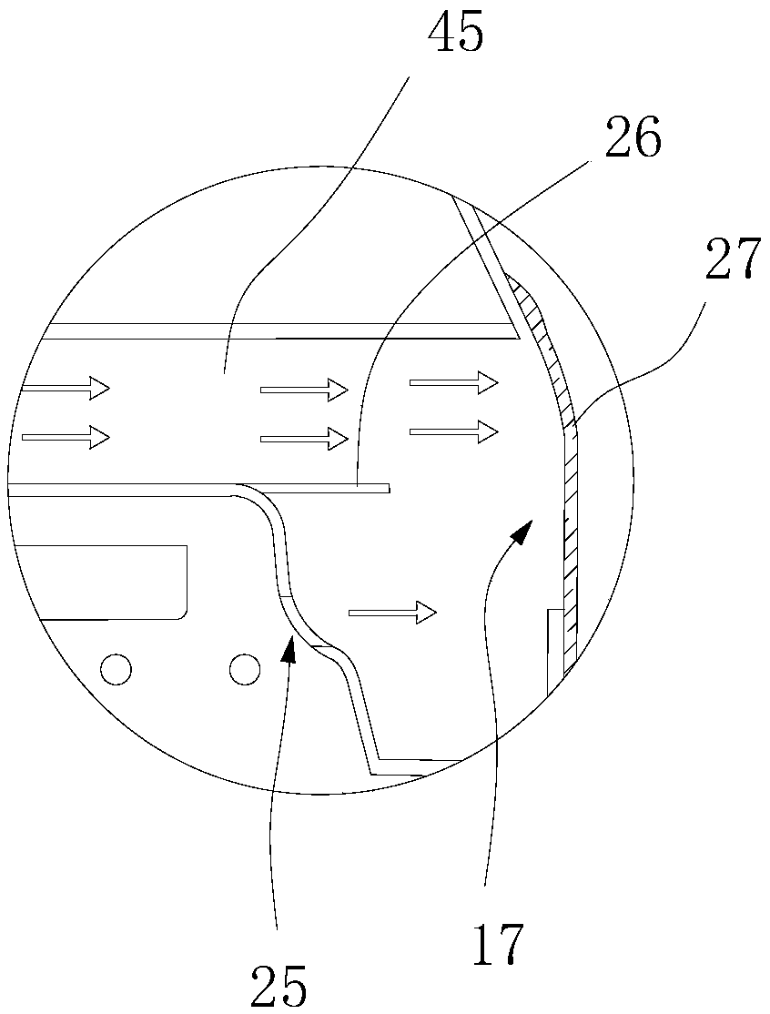
[0055] The difference between this embodiment and embodiment 1 is that, as figure 2 As shown, the blower hood 21 of the food preparation chamber is provided with a water vapor outlet 25, and the water vapor outlet 25 is used to discharge excess water vapor during the food preparation process, so as to avoid the air pressure in the food preparation chamber rising during the process of heating the air to bake the food. High, water vapor condensation causes phenomena such as food surface softness; A dividing plate 26 is arranged between the water vapor outlet 25 and the air outlet 45 of the draft hood 41, and the upper air outlet completely covers the water vapor outlet 25 and the air outlet 45, and the two gases are respectively discharged from the upper air outlet 17, preferably, A grille cover 27 embedded in the upper casing is provided at the position of the upper air outlet.

Embodiment 3

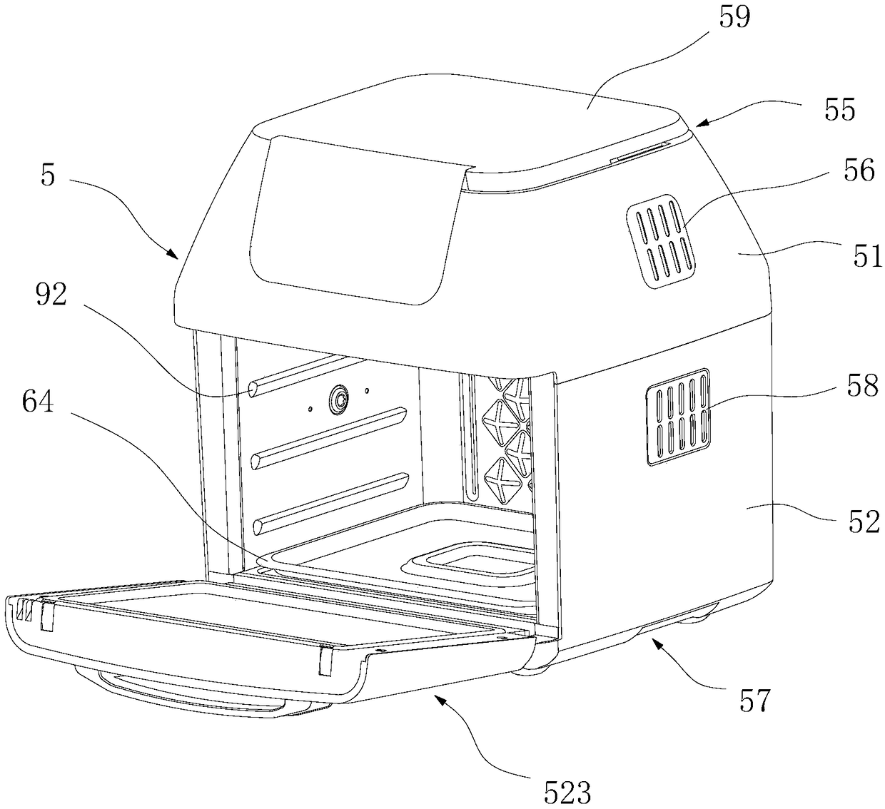
[0057] This embodiment provides an electric cooking appliance, such as image 3 As shown in -12, it uses a segmented heat dissipation structure to dissipate heat, specifically including a housing 5 , a food preparation chamber 6 , a heating device 7 , an air-inducing device 8 and a carrying device 9 .

[0058] Wherein, the casing 5 is a vertical structure, specifically comprising an upper casing 51, a lower casing 52 and a liner 53, wherein the liner 53 is arranged between the upper casing 51 and the lower casing 52, and the upper casing 51 It is separated from the lower case 52 , and the gas between the upper case 51 and the lower case 52 is close to or not exchanged or circulated at all.

[0059] The food preparation chamber 6 is located in the inside of the lower housing 52, and the food preparation chamber 6 top is covered with a blast hood 61, and the heating device 7 is located in the blast hood 61, and the heating device 7 includes a blast wind wheel 71 and an electric ...


PUM


Abstract

The invention provides electric cookware with an efficient heat dissipation function. The electric cookware comprises a casing, a food making chamber formed in the casing and a heating device arrangedin the food making chamber, wherein the casing comprises an upper casing, a lower casing and a liner plate arranged between the upper casing and the lower casing; the food making chamber is formed inthe lower casing and has a side wall, an air interlayer is formed between the lower casing and the side wall, the liner plate is arranged at the top of the air interlayer, the lower casing is provided with a lower air inlet and a lower air outlet, and air flows into the air interlayer from the lower air inlet and flows out of the lower air outlet; the food making chamber is covered with a blast hood, the heating device is arranged in the blast hood, and an accommodating space is formed among the liner plate, the upper casing and the blast hood; the upper casing is provided with an upper air inlet and an upper air outlet, an air induction device is arranged in the accommodating space, and air is forced by the air induction device to flow into the accommodating space from the upper air inlet and flows out of the upper air outlet. Harmful heat is discharged by segmented heat dissipation, and the electric cookware is simple in structure and has good heat dissipation effect.

Description

technical field [0001] The invention belongs to the field of intelligent home appliance manufacturing, and in particular relates to an electric cooking appliance with high heat dissipation. Background technique [0002] In the process of using high-temperature air flow to make food, the high-temperature air flow carries a large amount of heat, and through contact with the surface of the food, the heat is transferred to the food to complete the cooking of the food; however, during the process of circulating the high-temperature air flow in the food preparation chamber , It will also increase the temperature of the outer wall around the food preparation room. As time goes by, the outer wall will transfer part of the heat to the shell, causing the shell to heat up. At this time, the heat transferred to this part of the shell needs to be discharged. [0003] On the other hand, the generation of high-temperature air flow is based on electrical components, such as motors. There ar...

Claims


Application Information

Patent Timeline
Patent Type & Authority Applications(China)
IPC IPC(8): A47J37/06
CPCA47J37/0641A47J37/0664
Inventor 程晓梁福林肖丙三
Owner FOSHAN SHUNDE KUFU ELECTRIC APPLIANCES CO LTD
Learn More