Ejection-absorbing hybrid refrigerating and heat pump unit and operating method thereof

A technology of composite refrigeration and heat pump units, applied in refrigerators, refrigeration components, heat pumps, etc., can solve the problem of low comprehensive thermal performance of absorption units, high outlet temperature, and limited application of jet-absorption composite refrigeration and heat pump units. question

Inactive Publication Date: 2015-06-03
BEIJING UNIV OF CIVIL ENG & ARCHITECTURE
View PDF8 Cites 14 Cited by
  • Summary
  • Abstract
  • Description
  • Claims
  • Application Information

AI Technical Summary

Problems solved by technology

When adding a part of low-temperature and low-pressure refrigerant vapor to the condenser to increase the cooling and heating capacity of the unit, due to the limitation of the condensation temperature, in order to meet the performance requirements of the ejector, the traditional jet-absorption compound refrigeration and heat pump unit cannot Do not increase the generation temperature of the generator, which greatly limits the application of injection-absorption compound refrigeration

Method used


Image

  • Ejection-absorbing hybrid refrigerating and heat pump unit and operating method thereof
  • Ejection-absorbing hybrid refrigerating and heat pump unit and operating method thereof
  • Ejection-absorbing hybrid refrigerating and heat pump unit and operating method thereof

Examples


Embodiment 1

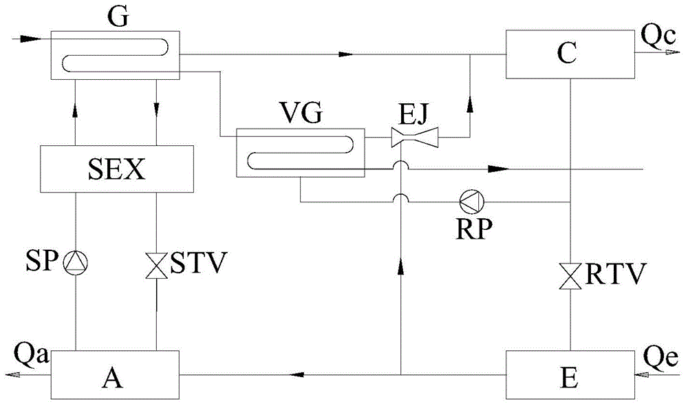
[0038] A jet-absorption compound refrigeration and heat pump unit, such as figure 1 As shown, including: generator G, condenser C, evaporator E, absorber A, solution heat exchanger SEX, solution pump SP, solution throttle valve STV, refrigerant throttle valve RTV, steam generator VG, gas Injector EJ;

[0039] Among them, the generator G is connected to the steam generator VG through the high-level heat source main pipeline, the steam outlet of the steam generator VG is connected to the working nozzle inlet of the gas injector EJ, and the outlet of the gas injector EJ is connected to the steam outlet of the generator G and the condensation The inlet of condenser C is connected, and the outlet of condenser C is divided into two routes: one is connected with the inlet of steam generator VG, and the other is connected with the inlet of evaporator E through refrigerant throttle valve RTV, and the outlet of evaporator E is divided into Two paths: one path is connected with the rece...

Embodiment 2

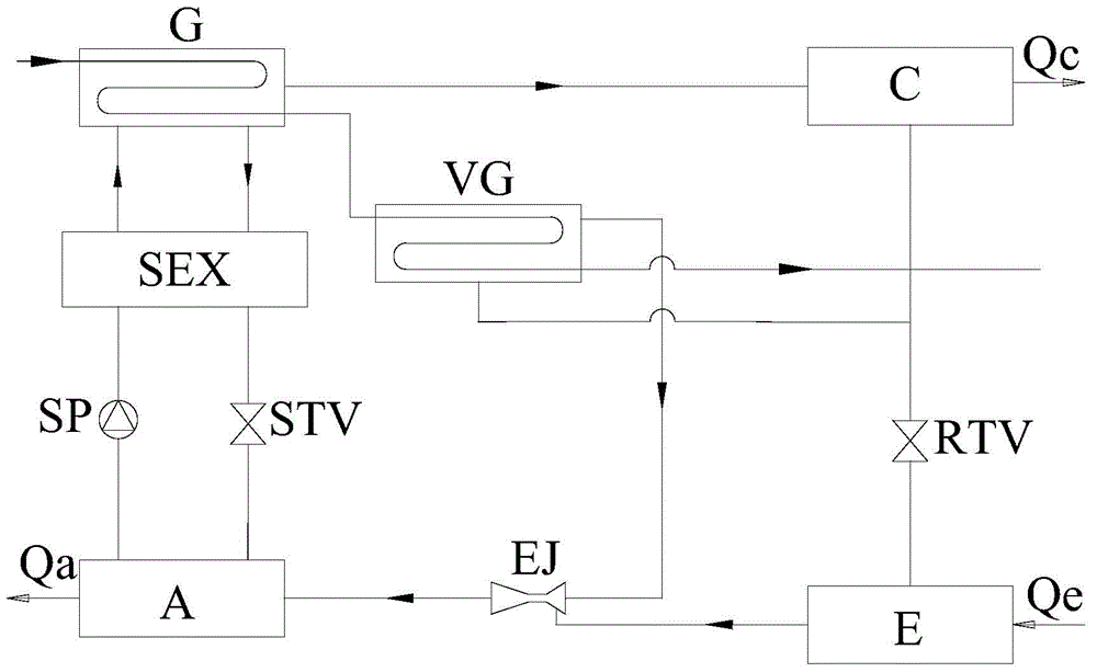
[0044] A jet-absorption compound refrigeration and heat pump unit, such as figure 2 As shown, including: generator G, condenser C, evaporator E, absorber A, solution heat exchanger SEX, solution pump SP, solution throttle valve STV, refrigerant throttle valve RTV, steam generator VG, gas Injector EJ;

[0045] Among them, the generator G is connected to the steam generator VG through the high-level heat source main pipeline, the steam outlet of the steam generator VG is connected to the working nozzle inlet of the gas injector EJ, and the outlet of the gas injector EJ is connected to the steam inlet of the absorber A, The dilute solution outlet of the absorber A is connected with the dilute solution inlet of the solution heat exchanger SEX through the solution pump SP, and the concentrated solution inlet of the absorber A is connected with the concentrated solution outlet of the solution heat exchanger SEX through the solution throttling valve STV, and the solution heat The d...

Embodiment 3

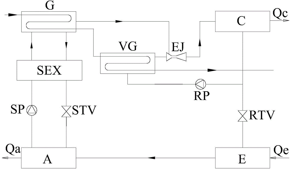
[0050] A jet-absorption compound refrigeration and heat pump unit, such as image 3 As shown, including: generator G, condenser C, evaporator E, absorber A, solution heat exchanger SEX, solution pump SP, solution throttle valve STV, refrigerant throttle valve RTV, steam generator VG, gas Injector EJ;

[0051] Among them, the generator G is connected to the steam generator VG through the high-level heat source main pipeline, the steam outlet of the steam generator VG is connected to the working nozzle inlet of the gas injector EJ, the outlet of the gas injector EJ is connected to the inlet of the condenser C, and the condensing The outlet of device C is divided into two routes: one is connected with the inlet of steam generator VG, and the other is connected with the inlet of evaporator E through refrigerant throttle valve RTV, and the outlet of evaporator E is connected with the steam inlet of absorber A, absorbing The dilute solution outlet of the absorber A is connected wit...


PUM


Abstract

The invention belongs to the technical field of refrigerating and heat pumps and particularly relates to an ejection-absorbing hybrid refrigerating and heat pump unit and an operating method thereof. The unit comprises generators, a condenser, an evaporator, an absorber, a solution heat exchanger, a solution pump, a solution throttle valve, a coolant throttle valve, a steam generator and a gas ejector. By providing one or multiple steam generators, outlet temperature of a high-level drive heat source of the unit can be decreased, utilization efficiency of heat and hierarchy of coolant steam pressure are increased, and the gas ejector can be conveniently set according to different pressure level; high-temperature high-pressure steam generated by the steam generator allow coolant steam to be ejected from outlets of the generators to the condenser, thereby decreasing the high-level heat source temperature of the generators; the coolant steam from an outlet of the evaporator can also be ejected to the absorber so as to enhance absorbing pressure of the absorber and reduce the size of the absorber; the coolant steam from the outlet of the evaporator can also be ejected to the condenser to increase refrigerating and heating quantity of the unit and improve comprehensive thermal performance of the unit.

Description

technical field [0001] The invention belongs to the technical field of refrigeration and heat pump, and in particular relates to a jet-absorption compound refrigeration and heat pump unit and its working method. Background technique [0002] When traditional injection-absorption composite refrigeration and heat pump units use gas ejectors, the high-temperature and high-pressure refrigerant vapor at the outlet of the generator is used as the working fluid to inject the low-temperature and low-pressure refrigerant vapor at the outlet of the evaporator. Or increase the absorption effect of the absorber by increasing the refrigerant vapor pressure at the inlet of the absorber; or increase the cooling and heating capacity of the unit by additionally introducing a part of low-temperature and low-pressure refrigerant vapor to the condenser. [0003] When the high-temperature and high-pressure refrigerant vapor at the outlet of the generator is used as the working fluid to introduce...

Claims


Application Information

Patent Timeline
IPC IPC(8): F25B30/00F22B33/18
CPCF22B33/18F25B25/02F25B30/00
Inventor 高岩程博胡文举
Owner BEIJING UNIV OF CIVIL ENG & ARCHITECTURE
Why Eureka
Try Eureka