
Wind flux concentration guiding device and engine room layout thereof

一种发动机室、风通量的技术,应用在发动机元件、机器/发动机、发动机的冷却等方向,达到提高进气性能、提高冷却性能、提高效率的效果

Active Publication Date: 2012-09-19
HYUNDAI MOTOR CO LTD +1
View PDF8 Cites 7 Cited by
  • Summary
  • Abstract
  • Description
  • Claims
  • Application Information

AI Technical Summary

Problems solved by technology

[0012] Therefore, the enlargement of the opening area of ​​the front end portion to increase the air intake must be limited by the degree of freedom in appearance, which is inevitably accompanied by a limitation on the use of wind to improve the cooling performance of the intercooler

Method used


Image

  • Wind flux concentration guiding device and engine room layout thereof
  • Wind flux concentration guiding device and engine room layout thereof
  • Wind flux concentration guiding device and engine room layout thereof

Examples


Embodiment Construction

[0037] Reference will now be made in detail to various embodiments of the invention, examples of which are illustrated in the accompanying drawings and described below. While the invention has been described in conjunction with exemplary embodiments, it will be understood that that description is not intended to limit the invention to those exemplary embodiments. On the contrary, the invention is intended to cover not only the exemplary embodiments, but also various alternatives, modifications, equivalents and others, which may be included within the spirit and scope of the invention as defined by the appended claims. implementation.

[0038]Exemplary embodiments of the present invention are described in detail below with reference to the accompanying drawings, and those skilled in the art can implement the exemplary embodiments in various ways, and the present invention is not limited to the exemplary embodiments.

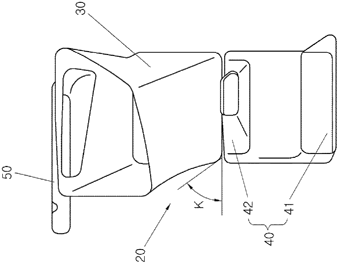
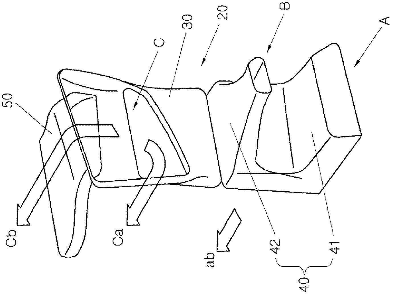
[0039] refer to Figure 1A In other words, the concentrated...


PUM


Abstract

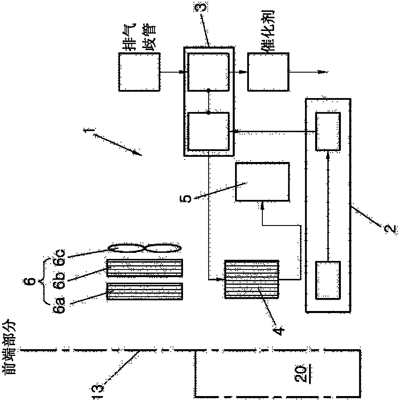
An engine room layout using a wind flux concentration guiding device, may include an intake system having an air intake, a turbocharger, and an intercooler, and may be disposed in an engine room, a cooling module having a condenser and a radiator, a main duct that introduces wind passing through a front end part forming the front of the engine room and discharges the wind to the air intake and the intercooler, a sub-duct that introduces the wind passing through the front end part from different positions and discharges the wind to the intercooler, and a diverging duct that may be connected to a wind channel of the main duct to diverge some of the wind introduced into the main duct before the wind passes out of the main duct, and send the wind to the air intake.

Description

[0001] Cross References to Related Applications [0002] This application claims priority from Korean Patent Application No. 10-2011-0021223 filed on March 10, 2011, the entire contents of which are hereby incorporated by reference for all purposes. technical field [0003] The present invention relates to a wind flux concentration guiding device, and more particularly to such a wind flux concentration guiding device capable of significantly improving the cooling of an intercooler by increasing the inflow of wind performance, and involves an engine compartment layout with an optimized layout. Background technique [0004] Usually, around the engine are arranged an intake duct which takes in the outside air passing through the air filter; an intake system which contains the intake manifold connected to the combustion chamber; condensation of the cooling device radiator; and a radiator of the engine cooling system, wherein the engine is arranged in the engine compartment. ...

Claims


Application Information

Patent Timeline
Patent Type & Authority Applications(China)
IPC IPC(8): B60K13/02B60K11/06
CPCB60K13/02B60K11/04B60K11/08F01P2001/005F01P2060/02F01P11/10B60K11/06Y10T137/85938B62D25/08
Inventor 南宗佑李宗勋金原植韩宗梡
Owner HYUNDAI MOTOR CO LTD
Learn More