
Second-level high-temperature gasification incineration system for rubbish

A waste, high-temperature technology, applied in incinerators, combustion types, combustion methods, etc., can solve the problems of energy waste, high manufacturing cost, low combustion temperature, etc., and achieve the effect of reducing cost, increasing calorific value, and avoiding energy waste.

Active Publication Date: 2016-02-17
广东博业热能供应有限公司
View PDF11 Cites 26 Cited by
  • Summary
  • Abstract
  • Description
  • Claims
  • Application Information

AI Technical Summary

Problems solved by technology

However, this garbage gasification and fly ash high-temperature melting treatment device has the following disadvantages or deficiencies: (1), the calorific value of gasification gas after garbage gasification is low, and in order to avoid producing a large amount of dioxins and furans, it uses a cyclone furnace to Combustion under the combustion of pulverized coal at high temperature makes the manufacturing cost of the equipment higher, and the use of high-quality pulverized coal for combustion not only leads to higher waste disposal costs, but also causes waste of energy; (2), only in fluidized bed gas Garbage feeding is carried out at one place of the chemical furnace, which makes the efficiency of garbage treatment low
However, this waste pyrolysis gasification incineration method has the following disadvantages or deficiencies: (1), the gasification gas after waste gasification has a low calorific value, and the temperature is lower after heat exchange with air, resulting in a lower combustion temperature in the combustion chamber. low, which will produce a large amount of dioxins and furans, causing environmental pollution; (2), only one place of the fluidized bed gasifier can be used for waste feeding, making the waste treatment efficiency low

Method used


Image

  • Second-level high-temperature gasification incineration system for rubbish

Examples


Embodiment approach

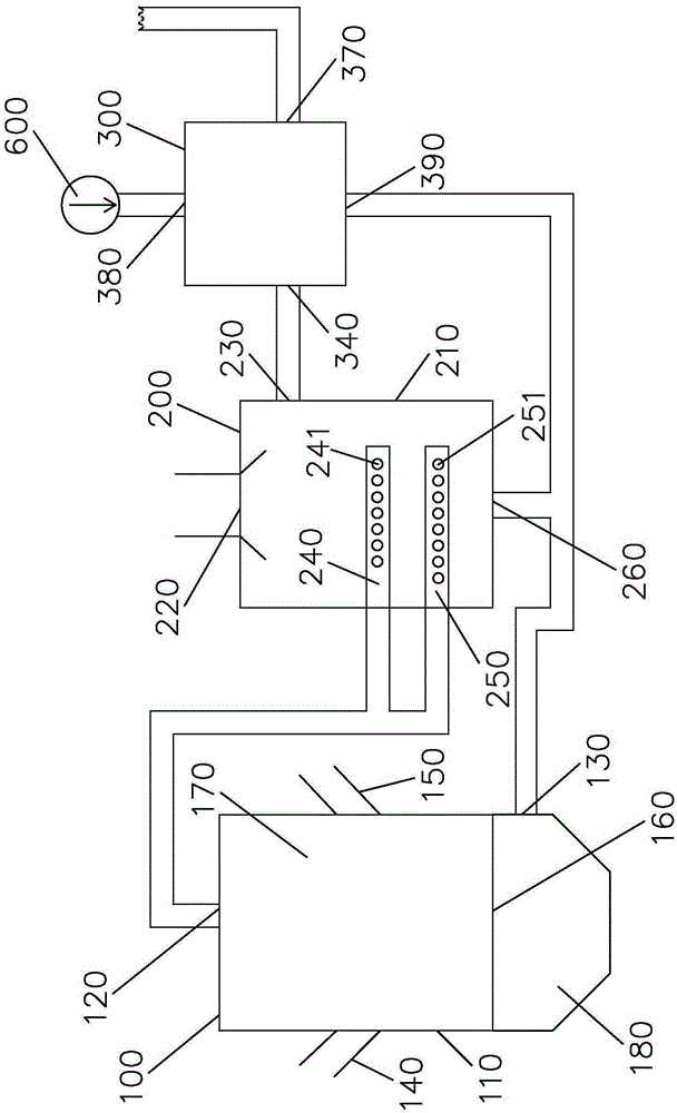
[0027] Please refer to figure 1 According to an embodiment of the present invention, the secondary high-temperature gasification and incineration system for waste includes: a fluidized bed gasification furnace 100 , an incinerator 200 and a high-temperature heat exchanger 300 .

[0028] Wherein, the fluidized bed gasification furnace 100 includes: a fluidized bed furnace body 110, a gasification gas outlet 120 arranged on the top wall of the fluidized bed furnace body, a primary air inlet 130 arranged at the bottom of the fluidized bed furnace body 110, and The primary garbage inlet 140 and the primary auxiliary fuel inlet 150 are arranged on the side wall of the fluidized bed furnace body 110 . The primary garbage inlet 140 is used to put primary garbage into the fluidized bed furnace body 110, and in this non-limiting embodiment, the primary garbage is domestic garbage. The primary auxiliary fuel inlet 150 is used to inject primary auxiliary fuel into the fluidized bed furn...


PUM


Abstract

The invention discloses a second-level high-temperature gasification incineration system for rubbish. The second-level high-temperature gasification incineration system comprises a fluidized bed gasification furnace and an incinerator. The fluidized bed gasification furnace comprises a gasified gas outlet formed in the top wall of a fluidized bed furnace body, a primary air inlet formed in the bottom of the fluidized bed furnace body, a first-level rubbish inlet and a first-level auxiliary fuel inlet. The interior of the fluidized bed furnace body is divided into a gasification room and an air room through an air distribution plate. The incinerator comprises a second-level rubbish and second-level auxiliary fuel feeding opening formed in the top wall of an incinerator body, a high-temperature smoke outlet formed in the side wall of the incinerator body, a first burning spray pipe arranged in the incinerator body and a secondary air inlet formed in the bottom wall of the incinerator body. The gasified gas outlet of the fluidized bed furnace body is communicated with the first burning spray pipe through a pipeline, and therefore gasified gas generated by first-level rubbish and first-level auxiliary fuel in the gasification room is conveyed into the incinerator, and second-level rubbish from the second-level feeding opening is incinerated at a high temperature under the assistance of second-level auxiliary fuel.

Description

technical field [0001] The invention relates to a garbage treatment system, in particular to a garbage high-temperature incineration system. Background technique [0002] With the rapid development of social economy and the continuous improvement of living standards, the output of various types of garbage has also increased sharply. At present, there are several common disposal methods of garbage, such as incineration, landfill and biological method. The landfill method requires the construction of a large area of ​​landfill and the treatment of leachate, which requires a large investment. The garbage biological method is to ferment domestic garbage, the process is complicated, the equipment performance requirements are high, and it has limitations. The waste incineration method is to use the combustible components in the waste to burn and gasify the waste to decompose the waste. It is a relatively efficient and cheap way to dispose of waste and is widely used by developed...

Claims


Application Information

Patent Timeline
IPC IPC(8): F23G5/027F23G5/08F23G5/46
Inventor 刘效洲苏晓键刘文星张宇栾殿利
Owner 广东博业热能供应有限公司
Learn More