Modular ceramic kiln energy-saving system of combined biomass gasifier

A technology for ceramic kilns and energy-saving systems, which is applied in the production of ceramic materials, furnaces, and furnace types, etc., can solve the problems of inability to realize gas stage regulation, inconsistent with the concept of green environmental protection, and increase equipment costs, so as to avoid air-fuel ratio imbalance. , the effect of simplifying the construction process and reducing the cost of equipment

Active Publication Date: 2016-02-17
QINGYUAN JINGWANG ENVIRONMENTAL PROTECTION EQUIP +1
View PDF8 Cites 4 Cited by
  • Summary
  • Abstract
  • Description
  • Claims
  • Application Information

AI Technical Summary

Problems solved by technology

However, this oxygen-enriched combustion-supporting energy-saving device for ceramic kilns has the following disadvantages or deficiencies: (1) It adopts an oxygen-enriched generation system, which increases the cost of the equipment on the one hand, and on the other hand, oxygen-enriched combustion will inevitably lead to a decrease in the carbon dioxide content in the flue gas. It is too high, which is contrary to the concept of carbon emission reduction vigorously advocated in the field of energy saving; (2), the gas pipe and air pipe adopt integrated control, which cannot realize the precise control of each section of the ceramic kiln
However, the energy-saving device on the ceramic kiln that can adjust the oxygen content of hot gas in sections has the following disadvantages or deficiencies: (1), it can only realize the segmented adjustment of the air intake, but cannot realize the segmented adjustment of the gas; (2) It uses gas as fuel, which is costly and does not conform to the concept of green environmental protection; (3) Its burner and kiln are integrally constructed, which is not conducive to adding or reducing burner modules at will according to the size of the ceramic kiln

Method used


Image

  • Modular ceramic kiln energy-saving system of combined biomass gasifier
  • Modular ceramic kiln energy-saving system of combined biomass gasifier

Examples


Embodiment approach

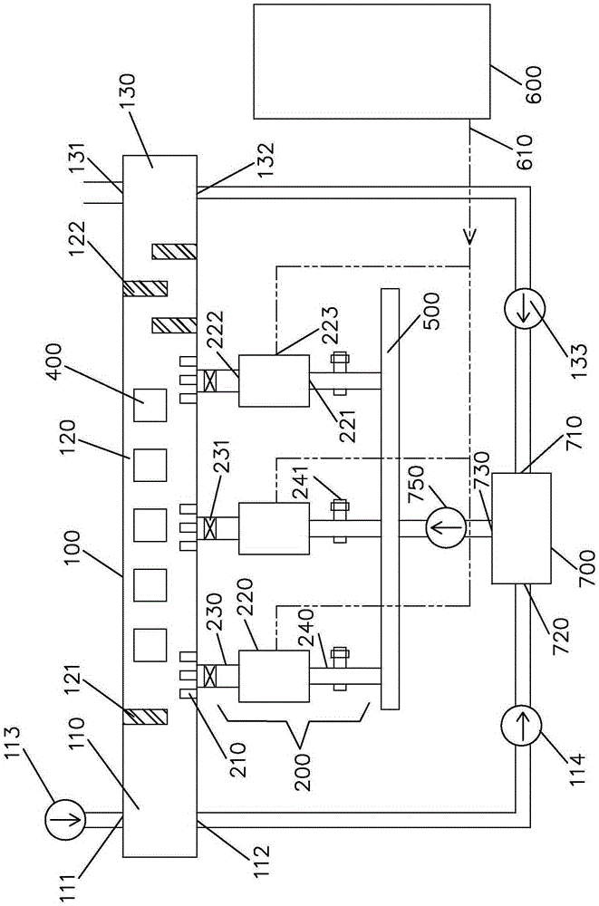
[0032] Please refer to figure 1, according to an embodiment of the present invention, a modular ceramic kiln energy-saving system combined with a biomass gasifier includes: a ceramic kiln 100 and three burner modules 200 .

[0033] Wherein, the ceramic kiln 100 is divided into a cooling section 110, a combustion section 120 and a preheating section 130 along the longitudinal direction, a first fire resistance wall 121 is arranged between the cooling section 110 and the combustion section 120, Three second fire resistance walls 122 are provided, and three burner modules 200 are connected to the side wall of the ceramic kiln 100 at equal intervals.

[0034] Wherein, the three burner modules 200 all adopt the same structure, and one of the burner modules 200 is used as an example for illustration below.

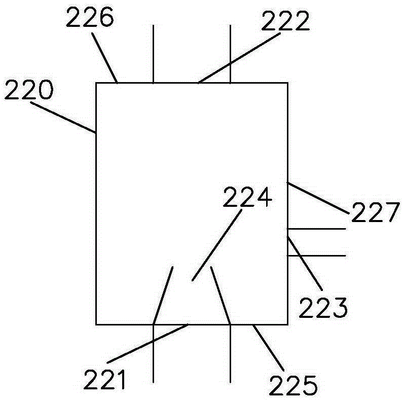
[0035] The burner module 200 includes: three burners 210 , an injection mixer 220 , a first connecting pipe 230 and a second connecting pipe 240 . The three burners 210 commun...


PUM


Abstract

The invention discloses a modular ceramic energy-saving system of a combined biomass gasifier. The modular ceramic energy-saving system comprises a ceramic kiln and at least two combustor modules. The ceramic kiln is divided into a cooling section, a combusting section and a preheating section in the longitudinal direction. The combustor modules are connected to the side wall of the ceramic kiln at intervals. Each combustor module comprises at least one burner, an ejecting mixer, a first connecting pipe and a second connecting pipe. The burners are arranged on the side wall of the ceramic kiln and used for ejecting fuel gas mixed gas into the combusting section to be combusted so that ceramic in the ceramic kiln can be heated. The ejecting mixers comprise combustion-supporting mixed gas inlets, fuel gas mixed gas outlets, biomass gas inlets and ejecting pipes. The ejecting mixers suck biomass gas from the biomass gas inlets, the biomass gas and combustion-supporting mixed gas form the fuel gas mixed gas in the ejecting mixers, and then the fuel gas mixed gas is conveyed to the burners through the first connecting pipes.

Description

technical field [0001] The invention relates to an energy-saving system for a kiln, in particular to an energy-saving system for a ceramic kiln. Background technique [0002] With the increasing market demand for ceramics, ceramic kilns are built longer and wider, and the cross-section is wider and wider. Firing defects such as deformation and color difference are also becoming more and more serious. [0003] At the same time, ceramic kilns often use gas as a heat source, and whether the ratio of gas to air during combustion is reasonable directly affects the energy consumption. When the amount of air is too small, the combustion is incomplete, and the incomplete combustion products contain a large amount of substances that pollute the environment, which also causes a waste of energy; and when the amount of air is too large, the excess air will take away a lot of heat when it is discharged, increasing the energy consumption. heat loss. [0004] In addition, fossil energy ...

Claims


Application Information

Patent Timeline
Patent Type & Authority Applications(China)
IPC IPC(8): F27B9/12F27B9/20F27B9/36F27B9/40F27B9/30
CPCY02P40/60
Inventor 刘效洲苏晓键刘文星张宇栾殿利
Owner QINGYUAN JINGWANG ENVIRONMENTAL PROTECTION EQUIP
Why Eureka
Try Eureka