
Power conversion system and power conversion method

一种功率转换系统、功率转换器的技术,应用在输出功率的转换装置、直流功率输入变换为直流功率输出、有中间变换为交流的变换设备等方向,能够解决较差线路调节率负载调节率等问题

Inactive Publication Date: 2016-02-17
MURATA MFG CO LTD
View PDF4 Cites 6 Cited by
  • Summary
  • Abstract
  • Description
  • Claims
  • Application Information

AI Technical Summary

Problems solved by technology

However, with a fixed duty cycle, the output voltage varies with the input voltage, possibly resulting in poor line and / or load regulation

Method used


Image

  • Power conversion system and power conversion method
  • Power conversion system and power conversion method
  • Power conversion system and power conversion method

Examples


Embodiment Construction

[0045] The present invention will be described in further detail below in conjunction with specific embodiments and accompanying drawings, but those skilled in the art will understand that the following description and accompanying drawings are only exemplary and should not limit the protection scope of the present invention. Components in the figures with the same or similar reference numbers may operate similarly. The specific structures shown in the drawings are only possible examples, and those skilled in the art can make modifications as required within the scope of the present invention without departing from the spirit and scope of the present invention.

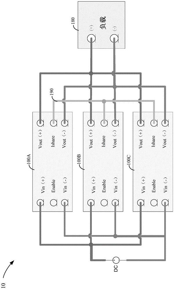
[0046] figure 1 A simplified block diagram of a power conversion system 10 according to one embodiment of the invention is shown. The power conversion system 10 may include at least two power converters 100 . By way of example and not limitation, figure 1 Three power converters 100A, 100B and 100C are shown in FIG....


PUM


Abstract

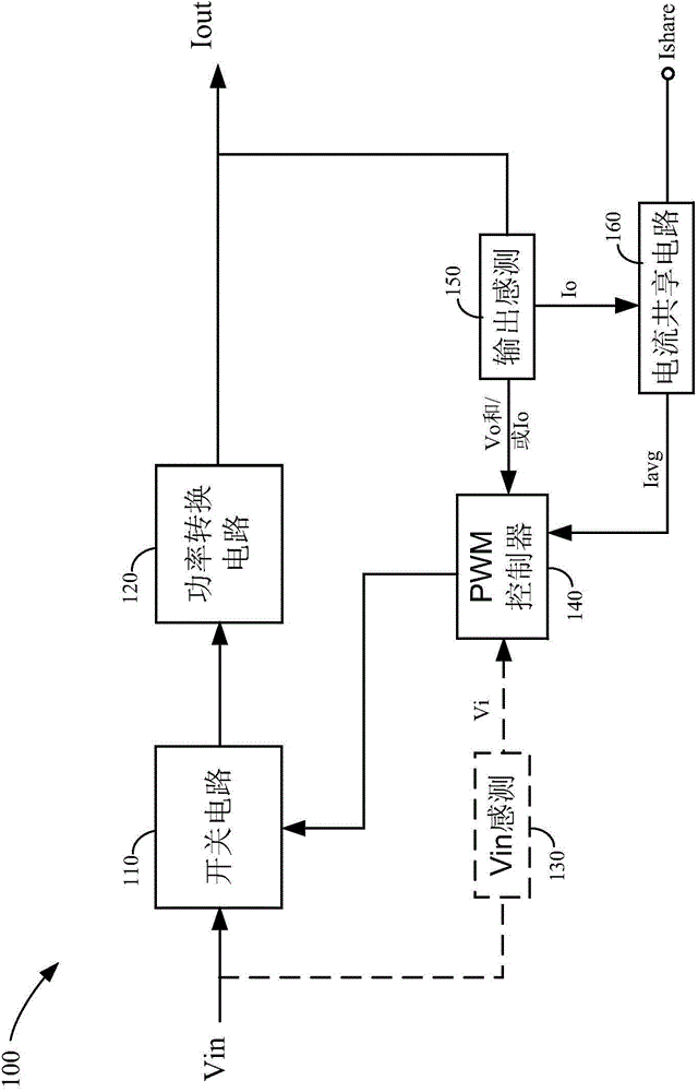
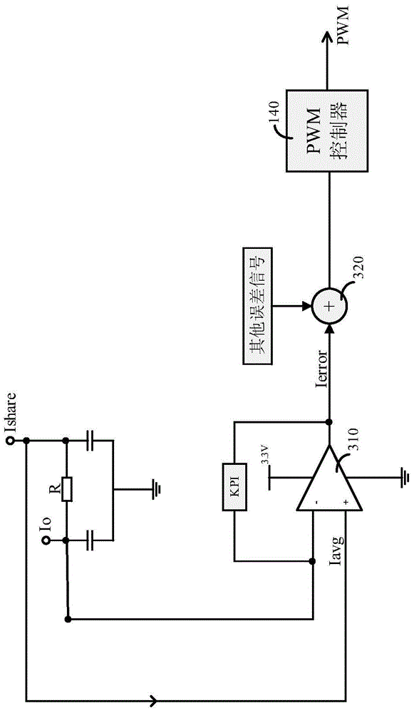
The invention discloses a power conversion system and a power conversion method. The power conversion system comprises at least two power converters and a current sharing bus. Each power converter includes a switching circuit, a power conversion circuit, an output sensing circuit, a current sharing terminal, and a PWM controller. The power conversion circuit is used for receiving an input voltage by the switching circuit and providing a local output current. The output sensing circuit is used for detecting the local output current and generating a local output current sensing signal correspondingly. The current sharing terminal is coupled to the local output current sensing signal by a resistor and is coupled to the current sharing bus. And the PWM controller is used for adjusting a duty ratio of the switching circuit at least partially based on the local output current sensing signal provided by the output sensing circuit and an average current signal on the current sharing bus. In addition, the invention also provides a control method for the power conversion system.

Description

technical field [0001] The invention relates to a power conversion system and a power conversion method, in particular to a duty ratio control system and a control method for a switching power supply. Background technique [0002] Since various applications have different power supply requirements, power converters, such as switching power supplies, are widely used in the field of electronics to provide the required voltage / current. The switching power supply maintains a stable voltage or current output at the output side of the power conversion circuit by controlling the on and off (and duty cycle) of the switching circuit at the input side of the power conversion circuit. Such a power conversion circuit can be implemented, for example, using a transformer, which converts the input voltage received by the primary side into an output voltage and current on the secondary side. [0003] In one aspect, it is desirable to increase the efficiency of such power converters, eg, th...

Claims


Application Information

Patent Timeline
Patent Type & Authority Applications(China)
IPC IPC(8): H02M3/10H02M3/28
CPCH02M3/285H02J1/102H02M3/33507
Inventor 曹宇王可志
Owner MURATA MFG CO LTD
Learn More