Double-direction precise hydraulic bar shearing machine and shearing method thereof

A shearing machine and bar material technology, applied in the direction of shearing devices, shearing machine equipment, metal processing equipment, etc., can solve the problems of inaccurate parking, tearing of the steel core of the shearing bearing, and asynchronous clamping wedges, etc. Achieve the effects of reducing production costs, improving work efficiency, and wide application range

Active Publication Date: 2016-02-24
沈阳恒佳忠祥液压设备有限公司
View PDF7 Cites 1 Cited by
  • Summary
  • Abstract
  • Description
  • Claims
  • Application Information

AI Technical Summary

Problems solved by technology

[0004] Through many tests so far, the reasons for the tearing of the heart are analyzed in three aspects: First: the friction clutch is affected by air pressure fluctuations and repeated startup of the friction plate, the friction plate heats up, and the friction coefficient of the friction plate changes due to heat, resulting in inaccurate parking , front and back, affecting the initial shear depth; second: the first two clamping wedges are not synchronized, and the feeding center will be changed; third: the screw rods at the front ends of the pistons of each cylinder are directly twisted into the driving parts, and the concentricity of the two cannot be controlled
Due to the above three reasons, the initial shear depth is seriously affected, so the steel core of the shear bearing is torn

Method used


Image

  • Double-direction precise hydraulic bar shearing machine and shearing method thereof
  • Double-direction precise hydraulic bar shearing machine and shearing method thereof
  • Double-direction precise hydraulic bar shearing machine and shearing method thereof

Examples


Embodiment 1

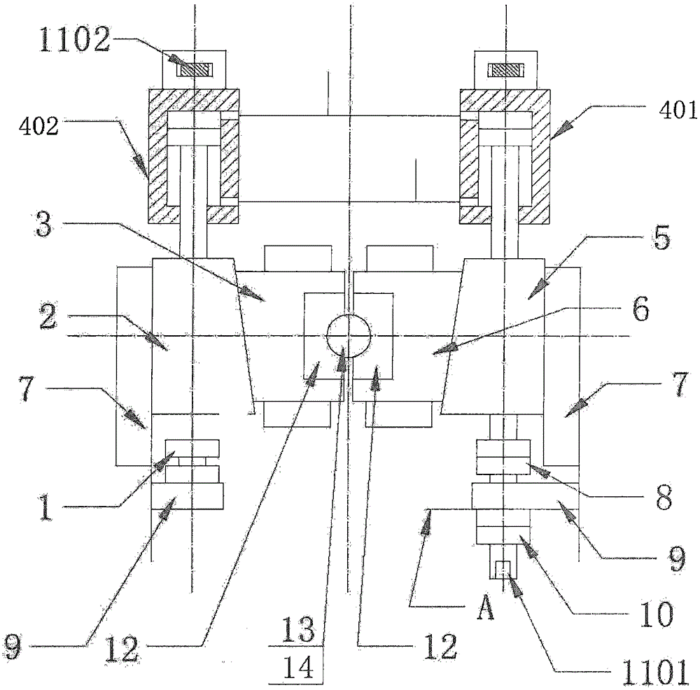
[0043] This embodiment provides a two-way precision hydraulic bar shearing machine and its shearing method. The method adopts two-way shearing: initial shearing, first cut a lunar arc (or semicircle) incision on the left side of the bar radial direction, so that A gap is cut in the radial surface hard layer, resulting in stress concentration and a slight lattice slip of the bar. The initial shear switch immediately activates the oil cylinder, and the direction of movement changes to the left, so that the rear knife cuts the bar along the gap, such as shearing Low-carbon steel has small radial deflection and small burrs; if high-carbon alloy steel (such as unannealed bearing steel) is sheared, the core will not tear.

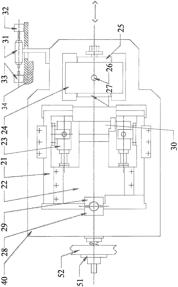
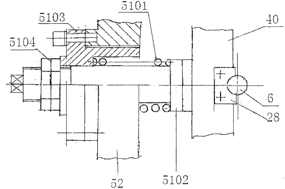
[0044] This embodiment specifically provides a two-way precision hydraulic bar shearing machine, including a slider 40, a front knife part, a rear knife part, a cutting depth adjustment part, a spring device 51, and the front knife part is used for centering the b...

Embodiment 2

[0073] This embodiment adopts the principle of two-way shearing, using the centering clamping of the front knife and the clamping of the rear knife. The structure, implementation mode and expected effect are the same as in Example 1.


PUM


Abstract

The invention provides a double-direction precise hydraulic bar shearing machine and a shearing method of the machine. At the beginning of shearing, a moon arc notch is cut in the radial left side of a bar, a gap is cut in the hard layer of the radial surface, stress concentration and slight bar lattice slippage are generated, a shear switch issues an order to an oil cylinder immediately, the motion direction is reversed to the leftward movement, a rear cutter shears off the bar along the gap, and for example, when low-carbon steel is shorn, the radial pressure skewness is small, and burrs are few; and if high-carbon alloy steel is shorn, the center portion cannot be torn off. The double-direction precise hydraulic bar shearing machine comprises a sliding block, a front cutter portion, a rear cutter portion, a shear depth adjusting portion and a spring device. The front cutter portion is used for centering and clamping the bar and is mounted on a front lathe, and the front cutter portion comprises a left wedge, a left cutter table, an oil cylinder, a right wedge, a right cutter table, a screw and blades.

Description

technical field [0001] The invention relates to bar shearing, and in particular provides a two-way precision hydraulic bar shearing machine and a shearing method thereof. Background technique [0002] At present, the shearing of bars at home and abroad adopts one-way shearing, one-time shearing, large shearing radial flattening, non-vertical cross-section, large burrs, and special shearing of high-carbon alloy steel such as GCr15 (bearing steel). cracked or torn. In order to solve this problem, the current bearing steel is heated and sheared. This method not only increases the requirements for production equipment (need to be equipped with a heating furnace), but also makes the power consumption remain high (a shear machine cuts 1000 tons of material and consumes 20 10,000 degrees); if a sawing machine is used for blanking, and a shearing machine cuts 1000 tons of material, the loss of steel at the saw kerf reaches more than 40 tons, which is a huge waste. [0003] Wang Hu...

Claims


Application Information

Patent Timeline
Patent Type & Authority Applications(China)
IPC IPC(8): B23D15/14B23D15/02
CPCB23D15/02B23D15/14
Inventor 王怀章
Owner 沈阳恒佳忠祥液压设备有限公司
Why Eureka
Try Eureka