A rotary drum flying shear

A flying shear and drum-type technology, which is applied in the field of steel rolling production, can solve the problems of enlarging the gap between cutting blades, complicated oil circuit, continuous cutting, etc., and achieve the effect of ensuring gapless connection, ensuring shearing effect, and stabilizing the overlapping amount

Active Publication Date: 2018-12-14
CISDI ENG CO LTD
View PDF6 Cites 0 Cited by
  • Summary
  • Abstract
  • Description
  • Claims
  • Application Information

AI Technical Summary

Problems solved by technology

[0007] 1) Due to the high-speed operation of the drum, the lubrication conditions of the supporting bearing of the drum are very strict, otherwise the bearing will be easily burned, and the figure 1 In the traditional high-speed flying shear structure shown, it is not easy to replace the bearing, especially on-site replacement is almost impossible, because the distribution gear 110 and distribution gear 111 on both sides of the drum have very strict meshing assembly requirements
Since there are bearings inside and outside the eccentric sleeve, the oil passage of the inner bearing is usually introduced through the outer bearing, the oil passage is complicated, and the lubrication state of the drum support bearing is affected by the support bearing of the eccentric sleeve
[0008] 2) Since the thickness of the shear strip is thin, the minimum thickness is less than 1mm, and the minimum clearance of the shear blade is 0.1mm to be smoothly sheared. figure 1 In the traditional high-speed flying shear structure shown, the clearance of the inner and outer bearings of the eccentric sleeve must be very small, otherwise the gap between the shear blades will be enlarged, resulting in serious accidents due to continuous shearing
[0009] 3) figure 1 The frame shown is directly fixed on the foundation, and it is difficult to repair the flying shears in case of failure, so it can be found in figure 1 The outside of the flying shear body shown is surrounded by a large frame. When a fault occurs, the flying shear body can be quickly pushed out of the line through an oil cylinder and other devices for easy maintenance, but this method requires a lot of investment
[0010] 4) Since the upper drum has no balance device, when shearing, there will be severe impact between the upper drum and the bearing, the upper eccentric sleeve and the bearing, which will have a great impact on the life of the bearing

Method used


Image

  • A rotary drum flying shear
  • A rotary drum flying shear
  • A rotary drum flying shear

Examples


Embodiment 1

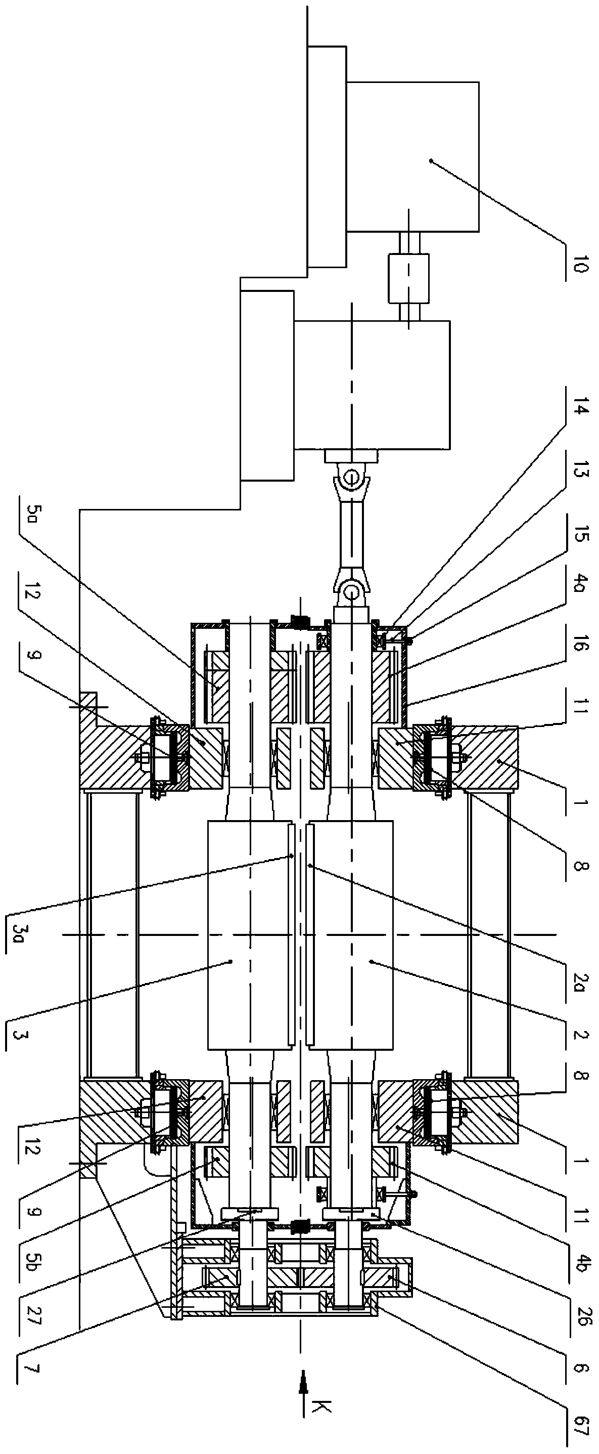
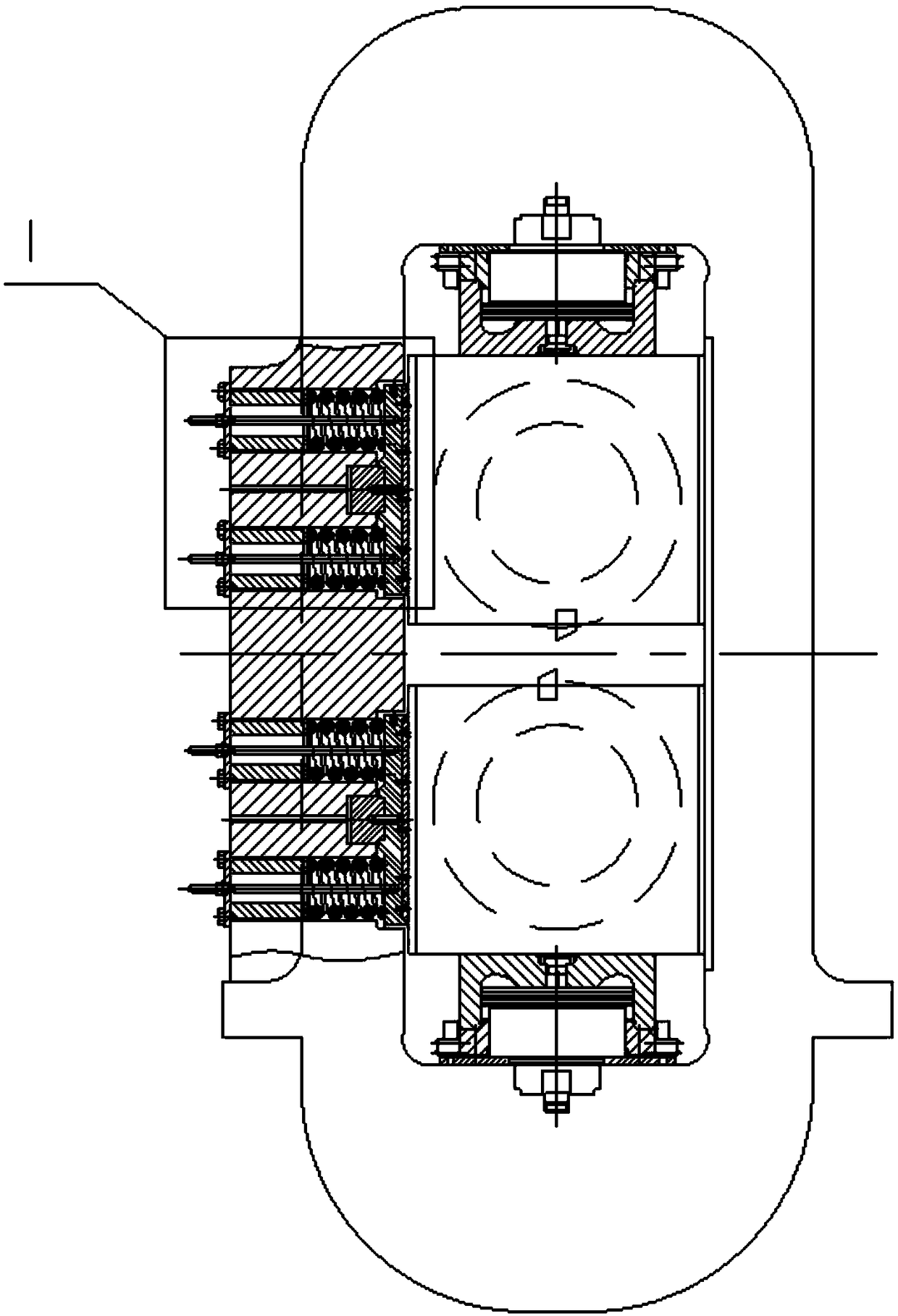
[0048] Such as figure 2 As shown, the present invention provides a drum-type flying shear, including a frame 1, a driving device 10, an upper drum assembly, and a lower drum assembly, and the upper drum assembly includes an upper bearing seat 11 and an upper bearing The upper drum 2 in the seat 11, the lower drum assembly includes the lower bearing seat 12 and the lower drum 3 installed in the lower bearing seat 12, the rotating outer circles of the upper drum 2 and the lower drum 3 are respectively installed with upper Cutting edge 2a and lower cutting edge 3a. The upper drum assembly and the lower drum assembly are installed in the frame 1, and the driving device 10 provides power for the upper drum assembly and the lower drum assembly. The frame 1 is equipped with an up and down push mechanism, and the up and down push mechanism is assembled with the upper drum. It is connected with the lower drum assembly, and can drive the upper drum assembly and the lower drum assembly...

Embodiment 2

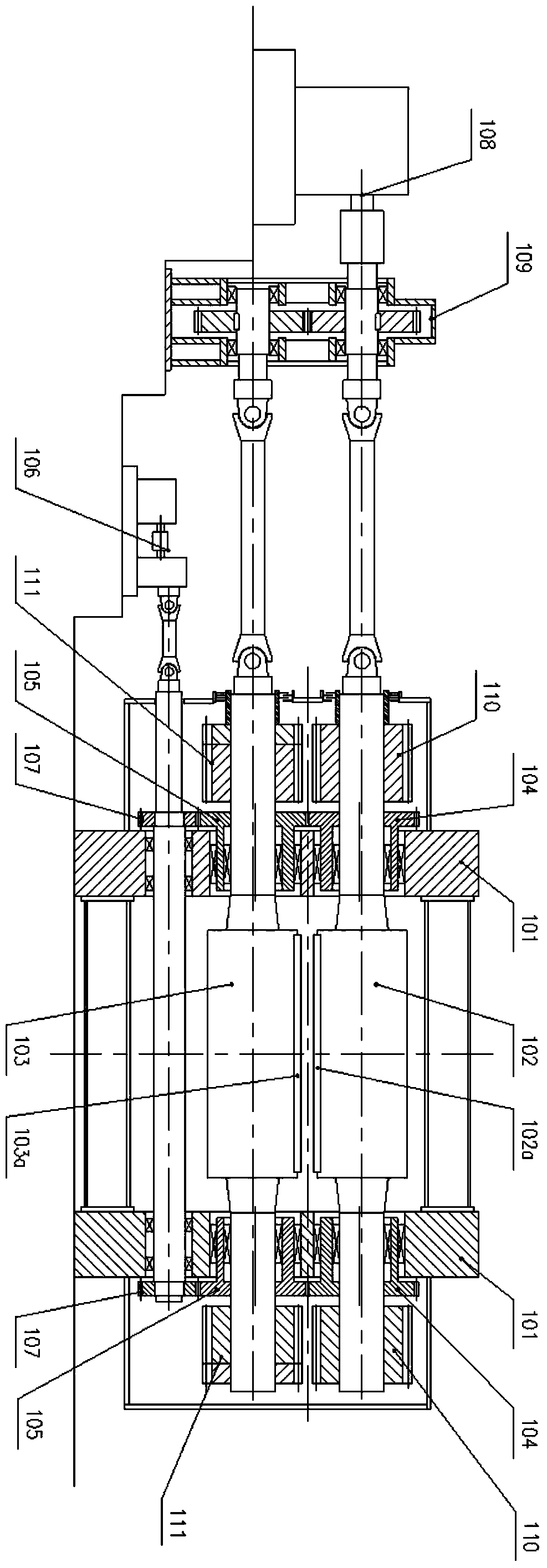
[0060] Such as Image 6 As shown, in this example, except that the distribution gear box 109 is moved to the transmission side, and the power of the driving device 10 is simultaneously transmitted to the upper drum 2 and the lower drum 3 through the distribution gear box 109, the structure is the same as that of the first embodiment. In this case, when the upper drum 2 and the lower drum 3 need to be replaced, the upper drum 2, the lower drum 3 and other parts can be dragged out of the line without dismantling the distribution gear box 109 for convenience. Blade replacement, blade clearance adjustment and equipment maintenance.

[0061] As mentioned above the present invention has the following advantages:

[0062] 1. Using hydraulic pressure as the driving force for reducing the center distance between the upper drum and the lower drum, and canceling the eccentric sleeve, it is convenient to control the relative movement of the upper drum and the lower drum, and at the same ...


PUM


Abstract

The invention provides a drum-type flying shear comprising a rack, a driving device, an upper bearing block, an upper drum, a lower bearing block and a lower drum, wherein the upper drum and the lower drum are provided with shearing blades; the rack is provided with a vertical pushing mechanism; the vertical pushing mechanism comprises an upper hydraulic cylinder and a lower hydraulic cylinder which are arranged inside the rack; the upper hydraulic cylinder is connected with the upper bearing block and can drive the upper drum to move downwards; and the lower hydraulic cylinder is connected with the lower bearing block and can drive the lower drum to move upwards. According to the drum-type flying shear, hydraulic pressure is used as power for reducing the central distance between the upper drum and the lower drum, and an eccentric bushing is omitted, so that the problems that a shearing gap cannot be ensured and a non-shearing accident is easily generated are avoided. The upper drum is suspended by a set of upper drum balancing device and is enabled to be always pressed on the top of an inner hole of the upper bearing block, so that a gap from the upper drum to the rack is eliminated. The upper drum and the lower drum are pressed to the other side of the rack by a pressing device arranged on the rack, so that a stable shearing blade gap required during shearing is ensured.

Description

technical field [0001] The invention belongs to the technical field of steel rolling production, and in particular relates to a drum type flying shear. Background technique [0002] The hot rolling production line adopting endless and semi-endless rolling technology can be cut at high speed after the finishing mill according to the plan, and coiled into steel coils with a certain coil weight at high speed. With this production method, multiple steel coils are produced, and there is only one strip threading and one tail throwing, which not only reduces operational accidents, but also improves the yield, and makes most of the strips rolled under stable tension. The shape accuracy is greatly improved. Among them, the function of high-speed cutting is completed by a set of high-speed flying shear equipment. [0003] Currently applied high-speed flying shear bodies such as figure 1 As shown, an upper drum 102 and a lower drum 103 are respectively supported in an upper eccentri...

Claims


Application Information

Patent Timeline
Patent Type & Authority Patents(China)
IPC IPC(8): B23D25/12B23D33/00
CPCB23D25/12B23D33/00
Inventor 方建忠黄焕江张赓郁
Owner CISDI ENG CO LTD
Why Eureka
Try Eureka