Retrieval box device

A technology of trays and shafts, applied in the field of tray-taking devices, can solve problems such as complex control systems and complex structures, and achieve the effects of improving production efficiency, reducing labor costs, and reducing the number of production workers

Active Publication Date: 2018-01-23
佛山市特福德自动化科技有限公司
View PDF8 Cites 0 Cited by
  • Summary
  • Abstract
  • Description
  • Claims
  • Application Information

AI Technical Summary

Problems solved by technology

In this way, not only the structure is complicated, but also the control system becomes complicated.

Method used


Image

  • Retrieval box device
  • Retrieval box device

Examples


Embodiment Construction

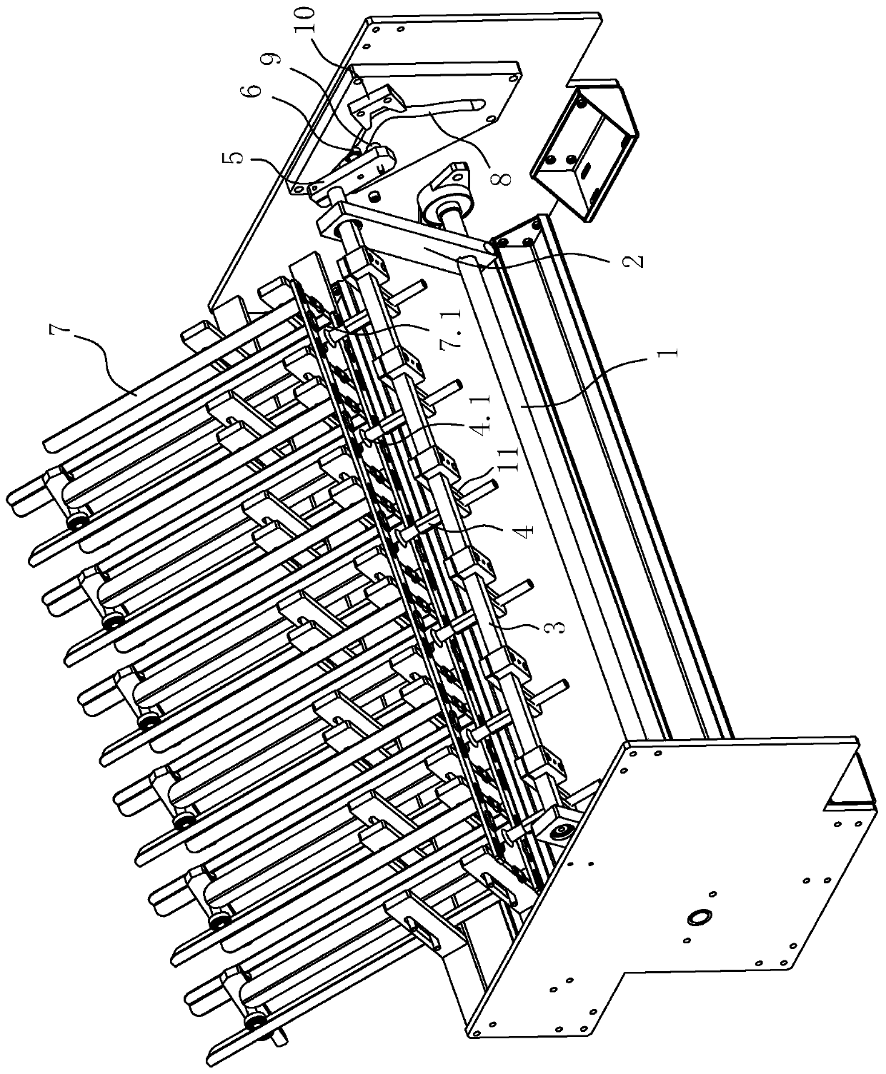
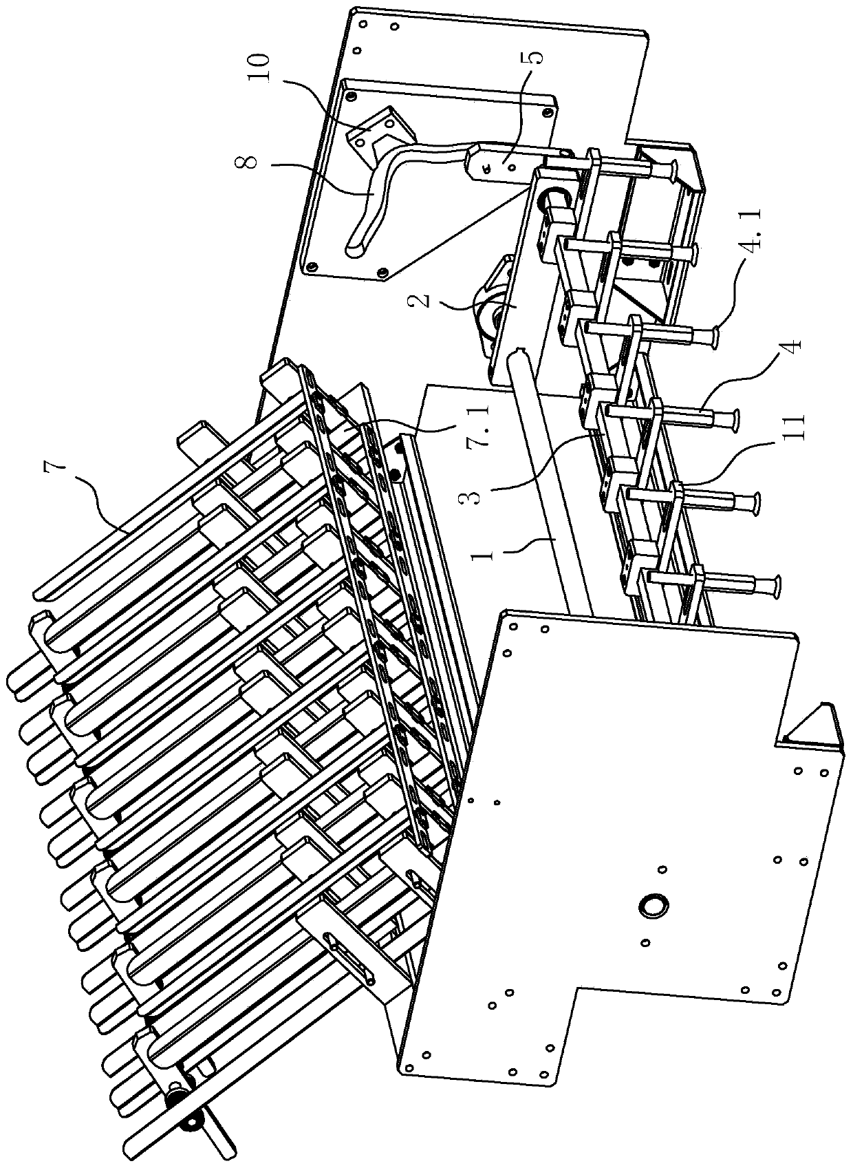
[0009] Such as Figure 1-2 As shown, a device for taking trays includes a revolving frame 2 that can be driven to rotate around a rotating shaft 1. A swinging shaft 3 that rotates parallel to the rotating shaft 1 is installed on the rotating frame 2. A suction cup manipulator is fixed on the swinging shaft 3. 4 and a crank 5, the crank 5 is equipped with a roller 6 that drives it to rotate, and the two sides above the rotating shaft 1 are respectively provided with a silo 7 for discharging the tray and a bellcrank-like slider for accommodating the movement of the roller 6. Rail 8, the corner of slide rail 8 is located at the center of the circle with rotating shaft 1, with the distance of swinging shaft 3 to rotating shaft 1 plus the distance of roller 6 to swinging shaft 3 as the radius, the crank 5 is at a certain distance from roller 6 A column pin 9 is installed at the extension end, and the outer side of the corner is fixed a stopper 10 that can block the column pin 9 and...


PUM


Abstract

The invention discloses a support box taking device. The support box taking device comprises a revolving frame, wherein a swing shaft is mounted on the revolving frame, and is fixed with a sucker manipulator and a crank; the crank is provided with a roller; a bin and a slide rail are respectively arranged at the two sides above the rotating shaft; a pin is mounted at an extension end of the crank; the outer side of a slide rail corner is fixed with a stopper capable of stopping the pin continuously moving forwards to enable the crank to rotate around the pin when the roller moves to the corner; and one end of the slide rail downwards extends to urge a sucker of the sucker manipulator to overturn to align to the lower side, and the other end extends to the bin to urge the sucker of the sucker manipulator to overturn to align to a tray outlet of the bin. The revolving frame, the crank and the slide rail form a rocker crank cam mechanism; and the synchronously fixed sucker manipulator is driven to overturn by using the turnover characteristics of the crank, so that a support box is swung onto a conveying belt at the lower side from the bin positioned at the side. The support box taking device realizes high-quality and high-efficiency support box conveying, greatly improves the production efficiency, and reduces the labor cost.

Description

technical field [0001] The invention relates to the technical field of packaging machinery, in particular to a tray removing device used in a tray packaging machine. Background technique [0002] In the modern packaging industry, such as bulk products of pastries and snacks, the products are usually individually packaged. After these products are produced, the products are first put into trays and then packaged to complete the independent packaging of the products. The traditional tray packaging machines manually discharge the trays on the conveyor belt, which is not only labor-intensive, but also inefficient. There are also mechanical take-out trays, but this kind of tray-taking mechanism has a simple structure, and is generally a simple circular-arc rotary mechanism. On the conveyor belt, it is difficult to guarantee the quality of the action. In order to ensure the quality of the action, an air cylinder will be installed to drive the suction cup to move back and forth t...

Claims


Application Information

Patent Timeline
Patent Type & Authority Patents(China)
IPC IPC(8): B65G47/91B65G47/04B65B61/00
CPCB65B61/00B65G47/04B65G47/90
Inventor 胡景红
Owner 佛山市特福德自动化科技有限公司
Why Eureka
Try Eureka