Modified intensive aeration and vein type biofilter

A biological filter, an improved technology, applied in the direction of sustainable biological treatment, reflux water treatment, water/sludge/sewage treatment, etc., can solve the problem of unsatisfactory removal of organic matter, limited removal of nitrogen denitrification, lack of exhaustion Oxygen and anoxic environment and other problems, to achieve good denitrification and denitrification, excellent decarbonization, and improve the treatment effect

Active Publication Date: 2016-02-24
西安聚光环保科技有限公司
View PDF6 Cites 12 Cited by
  • Summary
  • Abstract
  • Description
  • Claims
  • Application Information

AI Technical Summary

Problems solved by technology

[0006] ①The traditional biological aerated filter is aerated and oxygenated directly from the bottom of the tank, so the whole biological filter bed is basically in an aerobic state during normal operation, so the main body of the bed is aerobic bacteria, and the removal effect on organic matter Better, but lack of anaerobic and anoxic environment, the denitrification and removal of nitrogen in sewage is extremely limited; and after adopting the operation mode of intensive aeration, because the main flow direction of the water body is in the form of top-down, so in the biological filtration The upper layer of the bed is mainly composed of aerobic bacteria, while the middle and lower part of the packing layer is mainly composed of anaerobic or anaerobic bacteria because oxygen is difficult to reach, so that the entire biological filter bed has the ability to degrade organic matter and at the same time The function of nitrification and denitrification denitrification;
[0007] ②The traditional biological aerated filter mostly adopts the support plate with filter head and filter cap. During the long-term operation, due to the continuous increase of the suspended solids, the large-scale reproduction of microorganisms and the shedding biofilm, the suppo...

Method used


Image

  • Modified intensive aeration and vein type biofilter
  • Modified intensive aeration and vein type biofilter
  • Modified intensive aeration and vein type biofilter

Examples


Embodiment (1)

[0039] Embodiment (1): municipal sewage treatment

[0040] A pilot plant of an improved intensive aeration and venous biofilter was set up in a municipal sewage treatment plant in Jiangxi. The material of the device is made of carbon steel for anticorrosion.

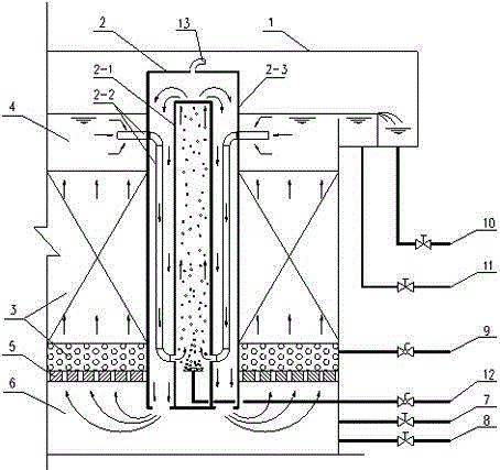
[0041] 1) The overall dimensions of the device are: L×W×H=1600mm×1600mm×2650mm, and the inner central area contains an intensive aeration and diversion circulation device;

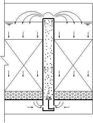
[0042] 2) The size of the outer guide cylinder of the intensive aeration and diversion circulation device is: ?800mm×2650mm, the size of the inner guide cylinder is: ?300mm×2250mm, and the size of the suction pipe connecting the inner and outer guide cylinders is DN80mm , a total of 6 are evenly distributed along the circumference, the upper suction port of each one is 250mm beyond the outer guide tube, and the size of the vent pipe above the outer guide tube is DN80mm;

[0043] 3) The height of the water distribution area at the bottom of the devic...

Embodiment (2)

[0048] Example (2): Treatment of industrial high-concentration wastewater (coking plant ammonia distillation wastewater)

[0049] A pilot plant of an improved intensive aeration and venous biofilter was set up in the sewage treatment plant of a coking plant in Jiangxi. The main body of the flow circulation device is made of stainless steel SUS304.

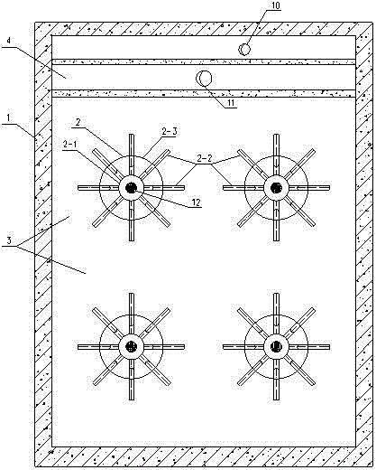
[0050] 1) The overall dimensions of the device are: L×W×H=2000mm×3500mm×3750mm, and the inner central area contains 2 intensive aeration and diversion circulation devices;

[0051] 2) The size of the outer guide cylinder of the intensive aeration and diversion circulation device is: ?1100mm×3650mm, the size of the inner guide cylinder is: ?400mm×3250mm, and the size of the suction pipe connecting the inner and outer guide cylinders is DN100mm , a total of 8 are evenly distributed along the circumference, the water suction port on each one is 350mm beyond the outer guide tube, and the size of the vent pipe above the outer guide tub...

Embodiment (3)

[0058] Example (3): Advanced treatment of petrochemical wastewater

[0059] Set up an improved intensive aeration and venous biofilter pilot plant in the sewage treatment plant of a petrochemical company in Shandong, which is compatible with the traditional upward flow biological aeration filter of a local engineering company in Shandong and the one of a company in Beijing The downflow internal circulation biological aerated filter competes in the same field. in:

[0060] 1) The pilot plant of the improved intensive aeration and venous biofilter provided is the same device as that used in the above example (1), and the main material is carbon steel for anticorrosion. The overall dimensions are: L×W×H=1600mm×1600mm×2650mm, and the inner central area contains an intensive aeration and diversion circulation device, in which the total amount of biological filler is 2m3;

[0061] 2) The overall dimensions of the upflow biological aerated filter provided by an enterprise in Shandong...


PUM

PropertyMeasurementUnit
Particle sizeaaaaaaaaaa
Heightaaaaaaaaaa
Heightaaaaaaaaaa

Abstract

The invention discloses a modified intensive aeration and vein type biofilter. The modified intensive aeration and vein type biofilter comprises a biofilter body (1). A water distribution region (6), a supporting layer (5), a biological filler region (3) and a coping water layer region (4) are arranged in the biofilter body. An intensive aeration and cyclic guiding device (2) is arranged in the biofilter body. The intensive aeration and cyclic guiding device comprises an inner guiding barrel (2-1), an outer guiding barrel (2-3) is arranged outside the inner guiding barrel, a breather pipe (13) is arranged at the upper end of the outer guiding barrel, and a water suction guide pipe (2-2) is arranged between the outer guiding barrel and the inner guiding barrel. The problems caused by the fact that the sewage flowing direction and the gravity direction of a traditional biofilter are the same are solved; low-concentration sewage cyclically treated once or more times can be fully mixed with original sewage, then the mixture is subjected to biological oxidation, the treatment effect is improved, and the biolfilter body has high adaptability to sewage with higher concentration and toxicity.

Description

technical field [0001] The invention relates to the field of sewage treatment, in particular to an improved intensive aeration and venous biofilter technology capable of simultaneously realizing high-efficiency biological decarburization and denitrification and excellent filtering effect. Background technique [0002] Biological aerated filter (BAF for short) is an aerobic wastewater treatment process based on the biological contact oxidation process by introducing the idea of ​​filtration in drinking water treatment. It appeared in Europe in the late 1970s and early 1980s. , Its outstanding feature is the combination of biological oxidation and filtration on the basis of the first-level intensive treatment. There is no sedimentation tank at the rear of the filter, and the periodic operation of the filter is realized by backwashing to remove the intercepted matter and excess biomass. This process not only has good performance in removing SS, COD, BOD, nitrification, phosphor...

Claims


Application Information

Patent Timeline
IPC IPC(8): C02F3/02
CPCC02F3/02C02F2301/04Y02W10/10
Inventor 刘微
Owner 西安聚光环保科技有限公司
Why Eureka
Try Eureka