
A Downhole Tool for Reducing Friction in Sliding Directional Drilling

A technology of directional drilling and downhole tools, which is applied in directional drilling, drilling equipment, drill pipes, etc., can solve the problems of high drilling cost, increased downhole friction, and no benefit, so as to reduce drilling construction costs and reduce slippage The effect of friction

Active Publication Date: 2017-12-22
CHINA PETROCHEMICAL CORP +3
View PDF6 Cites 0 Cited by
  • Summary
  • Abstract
  • Description
  • Claims
  • Application Information

AI Technical Summary

Problems solved by technology

[0002] In recent years, with the continuous deepening of domestic shale gas development and the wide application of cluster horizontal well drilling mode, many complex three-dimensional directional wells and horizontal wells with long horizontal sections have appeared, resulting in the increase of downhole friction and easy drilling during sliding directional drilling. Encountered back pressure problems, which caused great obstacles to normal directional construction
This kind of problem is dealt with by conventional methods, such as improving the performance of drilling fluid, reaming, well washing, etc., the effect is mediocre and it will consume a lot of production time
For example, the selection of rotary steerable, hydraulic oscillator, top drive sliding drilling control system and other solutions can solve the problem, but it is expensive to use, which will increase the drilling cost without benefit

Method used


Image

  • A Downhole Tool for Reducing Friction in Sliding Directional Drilling
  • A Downhole Tool for Reducing Friction in Sliding Directional Drilling
  • A Downhole Tool for Reducing Friction in Sliding Directional Drilling

Examples


Embodiment Construction

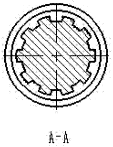
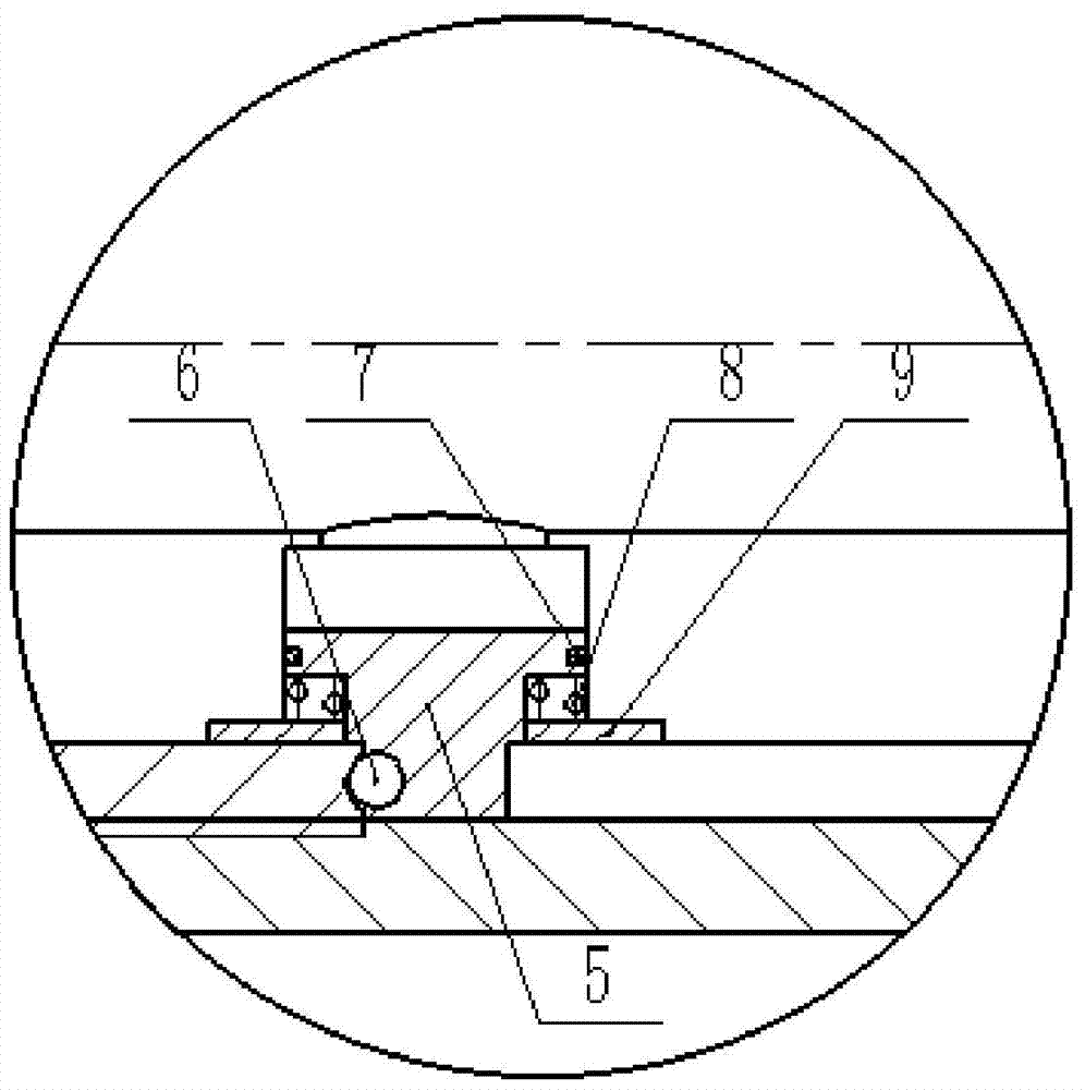
[0020] In order to have a clearer understanding of the technical features, purposes and effects of the present invention, the specific implementation manners of the present invention will now be described in detail with reference to the accompanying drawings.

[0021] like Figure 1-Figure 5 As shown, the downhole tool for reducing sliding and directional drilling friction of the present invention includes an upper joint 1, an upper outer cylinder 3, an upper mandrel 10, a lower joint 17, a lower outer cylinder 11 and a lower mandrel 16, and the upper joint 1 and the upper outer The cylinder 3 is fixedly connected, the lower joint 17 is connected with the lower mandrel 16, the upper outer cylinder 3 and the lower outer cylinder 11 are fixedly connected, the upper mandrel 10 is located in the upper outer cylinder 3, and the lower mandrel 16 is located in the lower outer cylinder 11. The female button end of the upper joint 1 is threadedly connected with the upper drilling tool,...


PUM


Abstract

The invention relates to a downhole tool capable of reducing drilling friction during sliding directional construction. The downhole tool comprises an upper joint, an upper outer cylinder, an upper mandrel, a lower joint, a lower outer cylinder and a lower mandrel. The upper joint is fixedly connected with the upper outer cylinder. The lower joint is connected with the lower mandrel. The upper outer cylinder is fixedly connected with the lower mandrel. The upper mandrel is located into the upper outer cylinder. The lower mandrel is located into the lower outer cylinder. An upper limiting block is arranged on eth upper mandrel. A lower limiting block is arranged on the lower mandrel. The upper limiting block is connected with a first spring. The lower limiting block is connected with a second spring.The downhole tool capable of reducing drilling friction during sliding directional construction has following beneficial effects: the downhole tool is of an all mechanical structure and can be switched between the 'off' state and the 'on' state; in the 'on' state, torque and drilling pressure can be transferred to a lower drilling rig without affecting drilling construction; in the 'off' state, an upper pipe column can freely rotate so that sliding friction can be significantly decreased and sliding directional drilling of the drilling rig below the tool is not affected; and by utilizing the tool, cost of drilling construction can be greatly reduced compared with conventional high-end technology including rotary steering.

Description

technical field [0001] The invention relates to the field of downhole drilling, more specifically, relates to a downhole tool for reducing sliding and directional drilling friction. Background technique [0002] In recent years, with the continuous deepening of domestic shale gas development and the wide application of cluster horizontal well drilling mode, many complex three-dimensional directional wells and horizontal wells with long horizontal sections have appeared, resulting in the increase of downhole friction and easy drilling during sliding directional drilling. Encountered pressure problems, causing great obstacles to the normal directional construction. This kind of problem is dealt with by conventional methods, such as improving the performance of drilling fluid, reaming, well washing, etc., the effect is general and it will consume a lot of production time. Such as the selection of rotary steerable, hydraulic oscillator, top drive sliding drilling control system...

Claims


Application Information

Patent Timeline
Patent Type & Authority Patents(China)
IPC IPC(8): E21B7/04E21B17/02
CPCE21B7/04E21B17/021
Inventor 彭小平何龙孙文常郝玉芬赵勇高云伟沈烁李奇尚琼李世勇
Owner CHINA PETROCHEMICAL CORP
Learn More