
Blowout preventer overhauling platform

A technology for overhauling platforms and blowout preventers, which is applied in drilling equipment, earth-moving drilling, drilling pipes, etc., can solve problems such as inability to lift cranes, hanging baskets, inconvenient overhaul, and high safety risks, so as to enhance construction safety and reduce The effect of labor intensity

Pending Publication Date: 2021-05-07
SINOPEC SSC +2
View PDF0 Cites 0 Cited by
  • Summary
  • Abstract
  • Description
  • Claims
  • Application Information

AI Technical Summary

Problems solved by technology

[0002] The position of the blowout preventer of the oil drilling rig is directly below the drilling floor, and the crane and basket cannot be used
The cumulative height of the blowout preventer group can reach six to seven meters, which is very inconvenient for maintenance. The blowout preventer is surrounded by a square well with a depth of four to five meters. Workers need to carry safety ropes to work, which poses a great safety risk
After searching the existing technology, there is no special mechanical device for oil drilling rig blowout preventer maintenance

Method used


Image

  • Blowout preventer overhauling platform
  • Blowout preventer overhauling platform
  • Blowout preventer overhauling platform

Examples


Embodiment 1

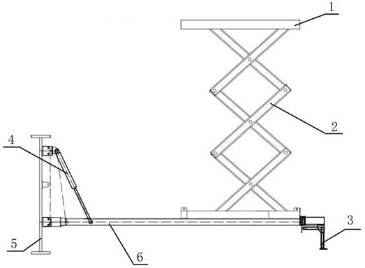
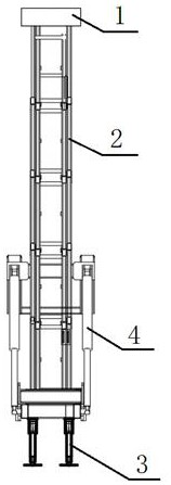
[0022] Embodiment 1, a blowout preventer maintenance platform, mainly composed of supporting legs 3, retractable arm 4, lifting base 6, arm frame 2 and working platform 1; The supporting leg 3 is installed at the other free end; the supporting leg 3 is hinged with the free end of the lifting base 6, and can freely rotate around the hinge axis to be perpendicular and parallel to the lifting base 6; one end of the retractable arm 4 is hinged with the lifting base 6 , the other end is provided with a hinged end with the derrick base 5, and the retractable arm 4 is a telescopic mechanism; when the retractable arm 4 is retracted, the lifting base 6 stands on the side of the derrick base 5, and the supporting legs 3 are recovered to be parallel to the lifting base 6 , when the retractable arm 4 is stretched out, the elevating base 6 is in a horizontal state, and the supporting leg 3 swings to be perpendicular to the free end of the elevating base 6; , the working platform 1 moves ve...

Embodiment 2

[0024] Embodiment 2, based on the basis of Embodiment 1, a group of connecting rods at the upper end of the boom 2 and the bottom of the working platform 1 form a sliding support through a chute, and a group of connecting rods at the lower end and the elevating base 6 pass through The rollers form a sliding support fit.

Embodiment 3

[0025] Embodiment 3, based on the basis of Embodiment 1, a group of connecting rods at the upper end of the boom 2 and the bottom of the working platform 1 form a sliding support through chute and rollers, and a group of connecting rods at the lower end and the lifting base 6 constitute sliding support cooperation by chute and roller above.

[0026] In the above embodiments, the telescoping mechanism is one of a hydraulic cylinder, a hydraulic cylinder or a linear drive screw. A safety valve is arranged in the pipeline of the hydraulic oil cylinder or the hydraulic cylinder. The safety valve includes one or more of a one-way valve, a flow regulating valve, a solenoid valve and an overflow valve.


PUM


Abstract

The invention discloses a blowout preventer overhauling platform. The blowout preventer overhauling platform is mainly composed of supporting legs, a retracting arm, a lifting base, an arm frame and a working platform. The working platform is installed at the top of the arm frame and moves vertically up and down along with lifting of the arm frame. When the retracting arm is retracted, the lifting base is erected on a derrick base; and when the retracting arm stretches out, the lifting base is in a horizontal state. The blowout preventer overhauling platform is a mechanical device facilitating overhauling of a blowout preventer, full-hydraulic control is adopted, the positions of the two sides of the blowout preventer can be overhauled correspondingly, and the blowout preventer overhauling platform can be retracted during the non-working period without affecting well drilling construction.

Description

technical field [0001] The invention relates to an oil drilling rig overhaul device in the field of oil drilling, in particular to a blowout preventer overhaul platform. Background technique [0002] The position of the blowout preventer of the oil drilling rig is located directly below the drilling floor, and cannot be hoisted or suspended. The cumulative height of the blowout preventer group can reach six to seven meters, which is very inconvenient for maintenance. The blowout preventer is surrounded by a square well with a depth of four to five meters. Workers need to carry safety ropes to work, which poses a great safety risk. After retrieving the prior art, there is no special mechanical device for oil drilling rig blowout preventer maintenance. Contents of the invention [0003] The purpose of the present invention is to overcome the deficiencies of the prior art and provide a blowout preventer inspection platform that adopts full hydraulic control, can inspect the ...

Claims


Application Information

Patent Timeline
IPC IPC(8): E21B19/00
CPCE21B19/00
Inventor 张振华刘海东孟强蔡文军李进付高煜曲刚邓霖王治娟孙晓哲
Owner SINOPEC SSC
Learn More