
Gas extraction method for region reinforcement of gob-side entry retaining

A technology of gas extraction and empty road retention, which is applied in gas discharge, mining equipment, earth-moving drilling, etc., can solve the problems of difficulty in forming holes, weak stability, and inability to continue gas extraction through drilling.

Active Publication Date: 2016-02-24
CHINA UNIV OF MINING & TECH
View PDF8 Cites 10 Cited by
  • Summary
  • Abstract
  • Description
  • Claims
  • Application Information

AI Technical Summary

Problems solved by technology

Although this method can reduce the amount of roadway excavation, there is a prominent problem in gas drainage by arranging boreholes in the roadway: when the caving method is used to fill the goaf, caving zones and fissure zones will be formed in sequence. and slow sinking zone
For the filling wall of the gob-side entry retention, the gas drainage drilling will pass through the collapse zone. The coal and rock in this area are broken and the stability is weak. It is difficult to form a hole during the construction of the gas drainage drilling. It is easy to collapse the hole, and the sealing effect of the drilled hole is poor
After a period of extraction, due to the low strength of coal and rock in this area, the borehole suffered shear and tensile failure under the action of mining stress, making it impossible to continue gas drainage in this borehole

Method used


Image

  • Gas extraction method for region reinforcement of gob-side entry retaining
  • Gas extraction method for region reinforcement of gob-side entry retaining

Examples


Embodiment Construction

[0017] An embodiment of the present invention will be further described below in conjunction with accompanying drawing:

[0018] The method of the present invention based on the reinforced gas drainage in the gobside entry retaining area, the specific steps are as follows:

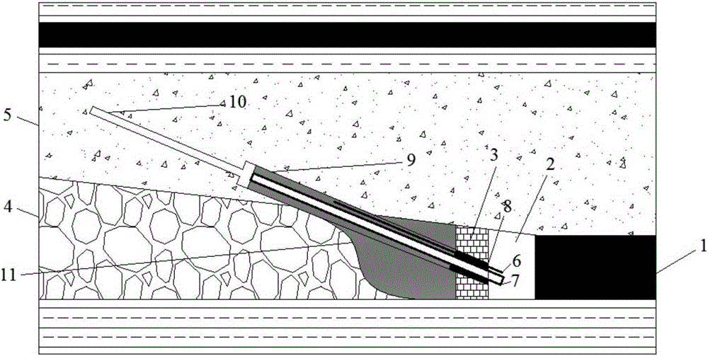
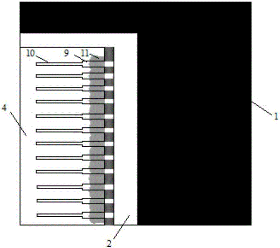
[0019] a. A gob-side entry 2 is formed between the coal body 1 and the filling wall 3, and a large borehole 9 is constructed on the side of the filling wall 3 of the gob-side entry 2 and passes through the collapse zone 4 toward the roof. The collapse zone 4 stops after entering the fissure zone 5 at a depth of 2 to 5 m; the diameter of the large boreholes 9 is 113 mm, and the distance between the opening positions of the large boreholes 9 is 5 to 10 m.

[0020] b. After drilling back, bind a grouting pipe 6 with an iron wire on the steel casing 7, and wrap polyurethane with a diameter of 94 mm on the steel casing 7 with a diameter of 94 mm and one end of the grouting pipe 6 for hole plugging with 8;

[...


PUM

PropertyMeasurementUnit
Diameteraaaaaaaaaa
Diameteraaaaaaaaaa
Diameteraaaaaaaaaa

Abstract

Provided is a gas extraction method for region reinforcement of gob-side entry retaining. The method comprises following steps: penetrating a large drilled hole of a caving zone towards the direction of a top plate along one side of a filling wall of gob-side entry retaining under construction, stuffing a steel sleeve pipe into the large drilled hole such that a grout outlet of a grouting pipe is located in the middle portion of the large drilled hole, closely adhering an expanded polyurethane located in a hole opening of the large drilled hole to a wall surface of the hole opening of the large drilled hole to seal the hole opening; and continuously moving forward to construct a small drilled hole along the interior of the steel sleeve pipe by grouting into the large drilled hole via the grouting pipe, stopping construction and performing drilling withdrawal when the small drilled hole is drilled at the pre-set depth, and connecting the steel sleeve pipe to an extraction pipeline for gas extraction. The gas extraction method for region reinforcement of gob-side entry retaining has following beneficial effects: a method is simple and has a great pore formation property; the likelihood of cutting and tensile fracture for drilled holes is decreased such that gas extraction operation can be performed continuously and stably; and a reinforcing area in the vicinity of gob-side entry retaining is formed in order to prevent a wall body against deformation due to stress concentration.

Description

technical field [0001] The invention relates to a method for strengthening and gas drainage in a strongly disturbed area, in particular to a method for strengthening gas drainage in a gob-side entry retaining area. Background technique [0002] The method of retaining roadway drilling can realize continuous mining, and it is a common method for gas control in coal seam group pressure relief mining at present. Although this method can reduce the amount of roadway excavation, there is a prominent problem in gas drainage by arranging boreholes in the roadway: when the caving method is used to fill the goaf, caving zones and fissure zones will be formed in sequence. and slow sinking zone. That is, after mining, the rock formation above the goaf collapses with the mining activities, and the area filled into the mining space is called the collapse zone; After the goaf is full, a large number of fissures will be produced under the action of rock pressure, but the integrity of the...

Claims


Application Information

Patent Timeline
IPC IPC(8): E21F7/00E21B33/13
CPCE21B33/13E21F7/00
Inventor 林柏泉杨威宋吴兵刘统王瑞黄展博梅晓凝
Owner CHINA UNIV OF MINING & TECH
Learn More