
Hydraulic coupler

A hydraulic coupler and volute technology, which is applied in the direction of fluid transmission, belt/chain/gear, mechanical equipment, etc., can solve the problem that cannot fully meet the requirements of high-speed rail vehicles, and the hydraulic coupler has a large volume and cannot reach Use requirements and other issues to achieve the effect of compact structure, fast response speed, and satisfying power transmission

Active Publication Date: 2016-02-24
CRRC DALIAN INST CO LTD
View PDF5 Cites 2 Cited by
  • Summary
  • Abstract
  • Description
  • Claims
  • Application Information

AI Technical Summary

Problems solved by technology

[0002] At present, the hydraulic transmission devices of domestic rail vehicles mostly use hydraulic torque converter + hydraulic torque converter. In the small and medium power level hydraulic transmission devices, the high-speed gear is not efficient due to the use of hydraulic torque converters. Requirements, unable to meet the requirements of high-speed rail vehicles and EMUs, it is necessary to use a hydraulic coupling instead of a hydraulic torque converter structure
Existing hydraulic couplings are large in size and not compact enough in structure. Natural cooling or fan forced cooling is generally used for heat generation during idling, and the oil discharge port is a radial straight port, which cannot fully meet the requirements of high-speed rail vehicles.

Method used


Image

  • Hydraulic coupler
  • Hydraulic coupler
  • Hydraulic coupler

Examples


Embodiment 1

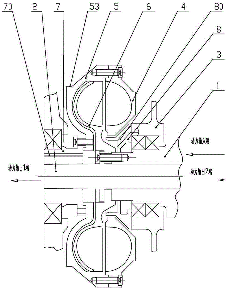
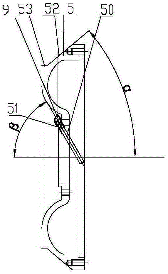
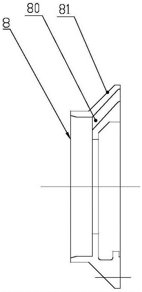
[0027] Such as Figure 1-4 The hydraulic coupling is used to connect the input shaft and the output shaft to transmit power. The input shaft 1 and the output shaft 2 are respectively supported on the box body 3 through bearings, wherein the input shaft 1 is a hollow shaft, and the output shaft 2 is a solid shaft. , the output shaft 2 is arranged inside the input shaft 1, wherein the output end of the power (that is, the output shaft) can be on the same side of the input shaft 1 or on the opposite side of the output shaft 2 .

[0028] The output shaft 2 is provided with a shaft sleeve 7, and the output shaft 2 is interference fit with the shaft sleeve 7. The hydraulic coupling includes a turbine 4, a volute 5 and a pump wheel 6 installed in the cavity formed by the turbine 4 and the volute 5. , the pump impeller 6 is fixedly connected with the input shaft 1, and the turbine 4 and the shaft sleeve 7 are both fixedly connected with the volute 5.

[0029] The volute 5 is matched ...

Embodiment 2

[0034] Such as Figure 5 As shown, the only difference between Embodiment 2 of the present invention and Embodiment 1 is that the input shaft 1 is a solid shaft, and the power output end (output shaft) can only be on the opposite side of the input shaft 1 .


PUM


Abstract

The invention discloses a hydraulic coupler which is used for connecting an input shaft and an output shaft. A shaft sleeve is arranged on the output shaft. The hydraulic coupler comprises a worm wheel, a volute, a pump impeller and an oil inlet tongue, wherein the pump impeller is mounted in a cavity formed by the worm wheel and the volute and is fixedly connected with the input shaft; the worm wheel and the shaft sleeve are fixedly connected with the volute; the hydraulic coupler is characterized in that an oblique oil outlet is formed in the volute and extends from the external part of the volute to the medial axis of the volute; one end of the oil inlet tongue is fixed in a box, and the other end of the oil inlet tongue is communicated to a gap between the worm wheel and the pump impeller; a first oil inlet is formed in the oil inlet tongue; a second oil inlet capable of extending in the axial direction of the shaft sleeve is formed in the shaft sleeve. The hydraulic coupler can rapidly discharge and feed oil and is high in cooling speed, compact in structure and steady in operation.

Description

technical field [0001] The invention relates to the field of shaft couplings, in particular to a hydraulic coupling. Background technique [0002] At present, the hydraulic transmission devices of domestic rail vehicles mostly use hydraulic torque converter + hydraulic torque converter. In the small and medium power level hydraulic transmission devices, the high-speed gear is not efficient due to the use of hydraulic torque converters. Requirements, can not meet the requirements of high-speed rail vehicles and EMUs, need to use hydraulic coupling instead of hydraulic torque converter structure. Existing hydraulic couplings are large in size and not compact enough in structure. Natural cooling or fan forced cooling is generally used for heat generation during idling, and the oil discharge port is a radial straight port, which cannot fully meet the requirements of high-speed rail vehicles. It is urgent to develop a fluid coupling with rapid oil filling and discharge, fast coo...

Claims


Application Information

Patent Timeline
IPC IPC(8): F16H41/04F16H41/24F16H41/26F16H41/28
CPCF16H41/04F16H41/24F16H41/26F16H41/28
Inventor 高恩芹庞洁
Owner CRRC DALIAN INST CO LTD
Learn More