
Electric connecting member

一种电连接件、电连接的技术,应用在连接、连接装置的零部件、电气元件等方向,能够解决生产效率低、过程费时繁琐、不利自动化生产等问题,达到安装简便、结构简单、便于自动化组装的效果

Active Publication Date: 2016-02-24
漳州立达信光电子科技有限公司
View PDF7 Cites 8 Cited by
  • Summary
  • Abstract
  • Description
  • Claims
  • Application Information

AI Technical Summary

Problems solved by technology

Due to the need for manual threading and welding of such a connection method, the production process is complicated, the production efficiency is low, the process is time-consuming and cumbersome, and it is not easy to position and install, which is not conducive to automated production

Method used


Image

  • Electric connecting member
  • Electric connecting member
  • Electric connecting member

Examples


Embodiment Construction

[0015] The present invention is elaborated below by specific embodiment:

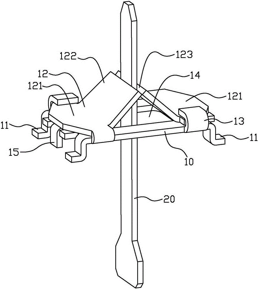
[0016] figure 1 It is a perspective view of the electrical connector of the first embodiment of the present invention. The electrical connector is used to realize the electrical connection between the light source board of the LED lamp and the drive board, and it includes a connecting board 10, which is connected with conductive pins 11, and the electrical connector is fixed on the The light source board is electrically connected with the light source board.

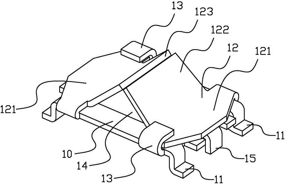
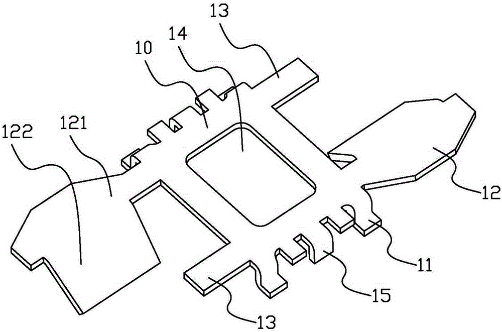
[0017] Please refer to Figure 1 to Figure 3 , in this embodiment, including four conductive pins 11, these conductive pins 11 are arranged around the connecting board 10, and these conductive pins 11 are bent downward from the side of the connecting board 10 to form a "Z" shape structure .

[0018] In addition, it also includes two electrical connecting pieces 12, each electrical connecting piece 12 includes a connecting portion 121 and an ab...


PUM


Abstract

The invention discloses an electric connecting member. The electric connecting member is used for realizing the electric connection of a light source plate and a driving plate of a light emitting diode (LED) lamp. The electric connecting member comprises a connecting plate. Electricity conductive pins are connected to the connecting plate. The electric connecting member is fixed to the light source plate and electrically connected with the light source plate through the electricity conductive pins. The electric connecting member further comprises two electric connecting pieces. Each electric connecting piece comprises a connecting part and an abutting part which are arranged integrally. One end of each connecting part is fixed to the connecting plate. The abutting parts of the electric connecting pieces are close to each other to form an elastic clamping part. The electric connecting member further comprises bendable fastening mechanisms. The fastening mechanisms abut against the other ends of the connecting parts after being bent so as to fix the connecting parts to the connecting plate. The electric connecting member has the advantages of being simple in structure and convenient to assemble automatically.

Description

technical field [0001] The invention relates to the lighting field, in particular to an electrical connector. Background technique [0002] With the improvement of global environmental protection awareness, LED lighting has been rapidly developed in the field of indoor lighting. In the current structure of the lamp cap of the LED lamp tube, the conductive connection from the electrode of the lamp cap to the driver board is mostly realized by manual welding of wires. Two wires are connected on the driver board and passed through the electrode pins and riveted to achieve the connection between the two poles of the drive power supply. the goal of. Due to the need for manual threading and welding of such a connection method, the production process is complicated, the production efficiency is low, the process is time-consuming and cumbersome, and it is not easy to position and install, which is not conducive to automated production. Contents of the invention [0003] In view ...

Claims


Application Information

Patent Timeline
Patent Type & Authority Applications(China)
IPC IPC(8): F21V23/06F21Y115/10
CPCF21V23/06H01R43/16H01R12/7076H01R12/718H01R13/113F21V19/003F21V23/004H01R12/7082
Inventor 曾茂进陈小波张湉董永哲鲍永均
Owner 漳州立达信光电子科技有限公司
Learn More