A test method for distributed capacitance of conductor system of large electrical equipment

A distributed capacitance and conductor technology, applied in the direction of measuring resistance/reactance/impedance, measuring devices, measuring electrical variables, etc., can solve problems such as complex capacitance distribution rules, achieve simple test methods, facilitate process-based operations, and suppress the introduction of errors Effect

Active Publication Date: 2019-06-28
CHINA EPRI ELECTRIC POWER ENG CO LTD +1
View PDF5 Cites 0 Cited by
  • Summary
  • Abstract
  • Description
  • Claims
  • Application Information

AI Technical Summary

Problems solved by technology

However, the distribution of distributed capacitance between multiple conductors is complex, and the error caused by the measurement effect needs to be controlled and evaluated

Method used


Image

  • A test method for distributed capacitance of conductor system of large electrical equipment
  • A test method for distributed capacitance of conductor system of large electrical equipment
  • A test method for distributed capacitance of conductor system of large electrical equipment

Examples


Embodiment Construction

[0042] The following describes in detail the embodiments of the present invention, examples of which are illustrated in the accompanying drawings, wherein the same or similar reference numerals refer to the same or similar elements or elements having the same or similar functions throughout. The embodiments described below with reference to the accompanying drawings are exemplary, and are intended to explain the present invention and should not be construed as limiting the present invention.

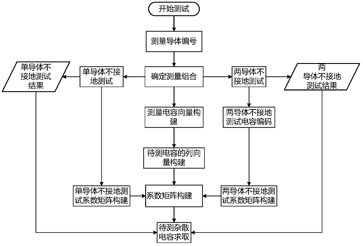
[0043] An example of a method for testing the distributed capacitance of a conductor system of large electrical equipment provided by the present invention is for example figure 1 shown, specifically:

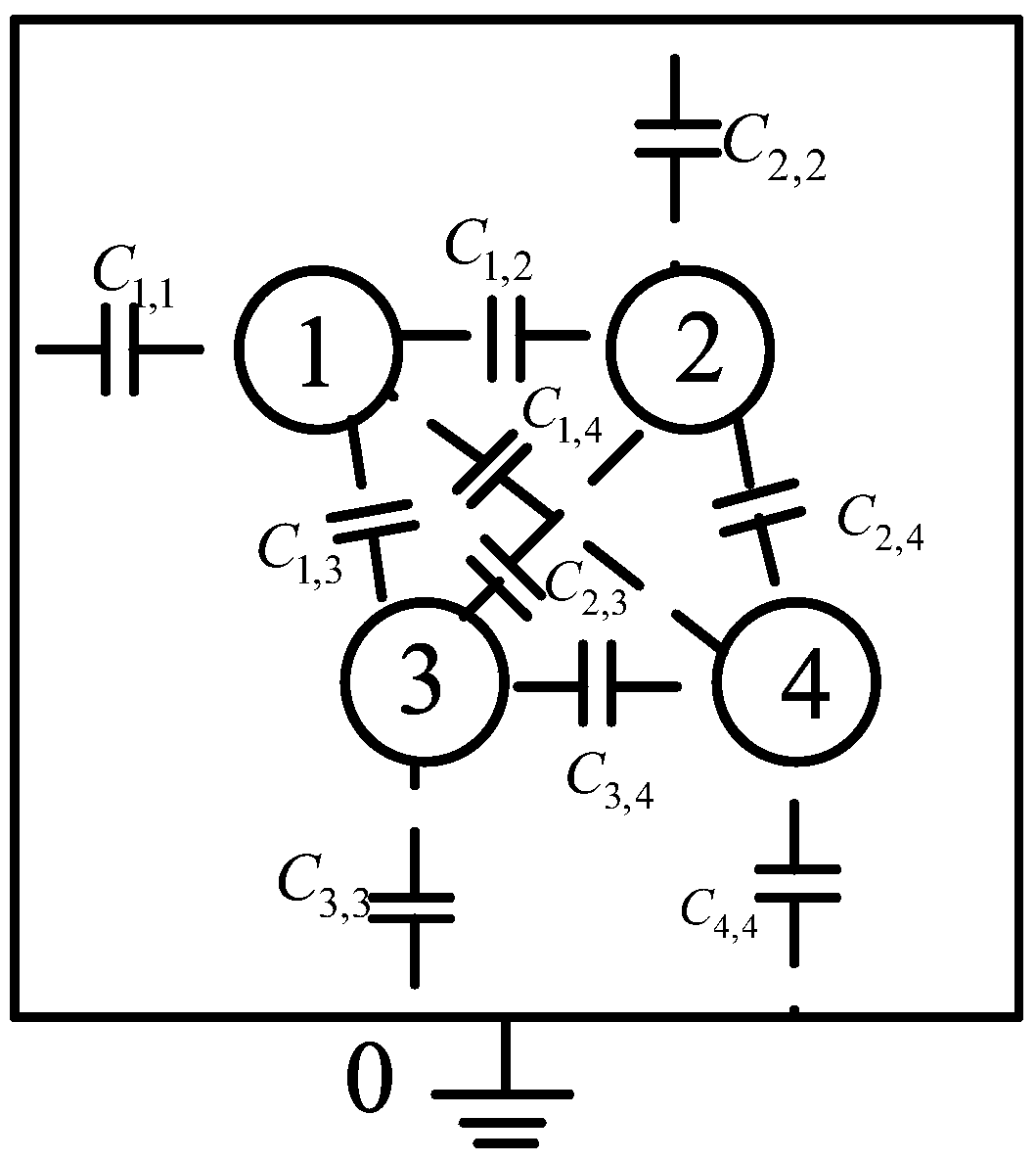
[0044] 1. Number all conductors to be tested in the conductor system. In this embodiment, the conductor system includes n+1 conductors, and n is at least 1.

[0045] In an electrostatically independent multi-conductor system, the relationship between the charged amount on each conductor...


PUM


Abstract

The invention provides a method for testing the distributed capacitance of a conductor system of large electrical equipment, comprising the following steps: step 1, numbering all conductors to be tested in a conductor system; step 2, carrying out single-conductor non-grounding test on the conductor system; step 3, carrying out two-conductor non-grounding test on the conductor system; step 4, building a measuring capacitor column vector; step 5, building a to-be-measured capacitor column vector; step 6, coding the parameters in the to-be-measured capacitor column vector; step 7, building a coefficient matrix of single-conductor non-grounding test; step 8, coding measuring conductors of two-conductor non-grounding test; step 9, building a coefficient matrix of two-conductor non-grounding test; and step 10, calculating the value of the to-be-measured capacitor column vector. Compared with the prior art, the method for testing the distributed capacitance of the conductor system of large electrical equipment provided by the invention is applicable to distributed capacitance test of a variety of large electrical equipment and can effectively suppress the influence of error introduced by measurement wiring.

Description

technical field [0001] The invention relates to the technical field of high-voltage equipment, in particular to a method for testing distributed capacitance of conductor systems of large-scale electrical equipment. Background technique [0002] The support and shielding system of large-scale electrical equipment contains a number of metal parts with complex structures, which form distributed capacitance in a specific arrangement, which needs to be represented by a complex n-dimensional matrix. The electrical equipment in operation needs to withstand various forms of impulse voltages from the operation of AC and DC systems, lightning, and steep waves. The existence of distributed capacitance will lead to uneven voltage distribution of each functional unit under the action of impulse voltage, and local accelerated aging due to excessive voltage, or even failure and damage. In addition, distributed capacitance is closely related to the structure of electrical equipment, and in...

Claims


Application Information

Patent Timeline
Patent Type & Authority Patents(China)
IPC IPC(8): G01R27/26
Inventor 刘杰纪锋董巍张娟娟高冲
Owner CHINA EPRI ELECTRIC POWER ENG CO LTD
Why Eureka
Try Eureka