

Step detection device and step detection method
A detection device and step technology, which is applied in the direction of measuring device, distance measurement, line-of-sight measurement, etc., can solve the problem of the decrease of the detection accuracy of the step position
- Summary
- Abstract
- Description
- Claims
- Application Information
AI Technical Summary
Problems solved by technology
Method used
Image

Examples
no. 1 approach
[0040] Next, embodiments will be described in detail with reference to the drawings.
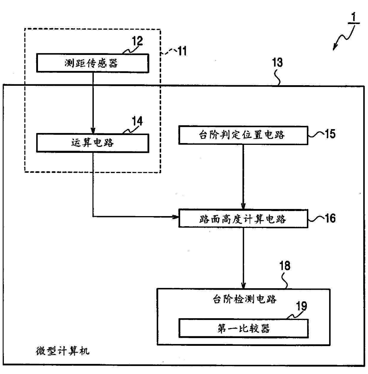
[0041] refer to figure 1 The overall configuration of the level difference detection device 1 according to the first embodiment will be described. The step detection device 1 detects the distance and orientation to the road around the vehicle and the surface of objects including curbstones on the road (hereinafter referred to as "road surface"), based on a plurality of lines set in the vehicle width direction of the road surface The height change of the road surface at the determination position of the step-shaped step is used to detect the step on the road surface.
[0042] Specifically, the step detection device 1 includes: a distance measuring sensor 12 that detects the distance and orientation to the road surface around the vehicle; Steps to a series of information processing microcomputers 13 .
[0043] An example of the ranging sensor 12 is a stereo camera capable of recording infor...
no. 2 approach
[0080] refer to Figure 7 The overall configuration of the level difference detection device 2 according to the second embodiment will be described. The step detection device 2 is at the first step judgment position (Pa 1 ) when the slope of the height change of the road surface is above the threshold value, the position is determined based on the first step (Pa 1 ) changes in the height of the road surface to detect steps (LD) on the road surface. Furthermore, in this case, in order to reduce the calculation load and increase the processing speed while maintaining the detection accuracy of the step, the step detection device 2 does not set the second step determination position (Pa 2 ), and the height change of the above-mentioned road surface at the second step determination position is not calculated.
[0081] Specifically, the road surface height calculation circuit 16 is equipped with the first step determination position (Pa 1 ) The second comparator 20 for comparing...
no. 3 approach
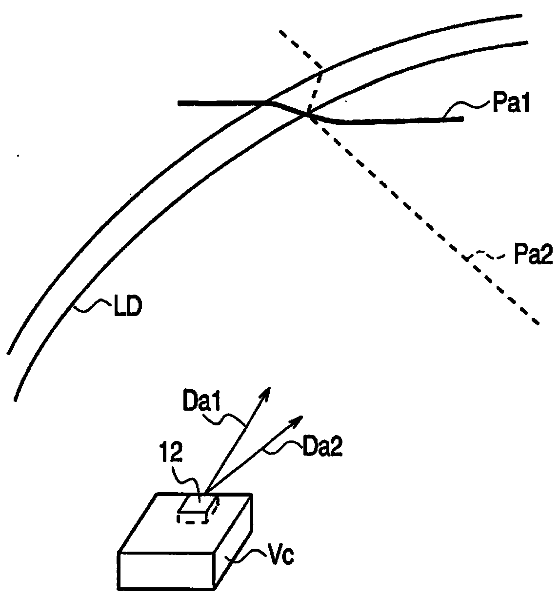
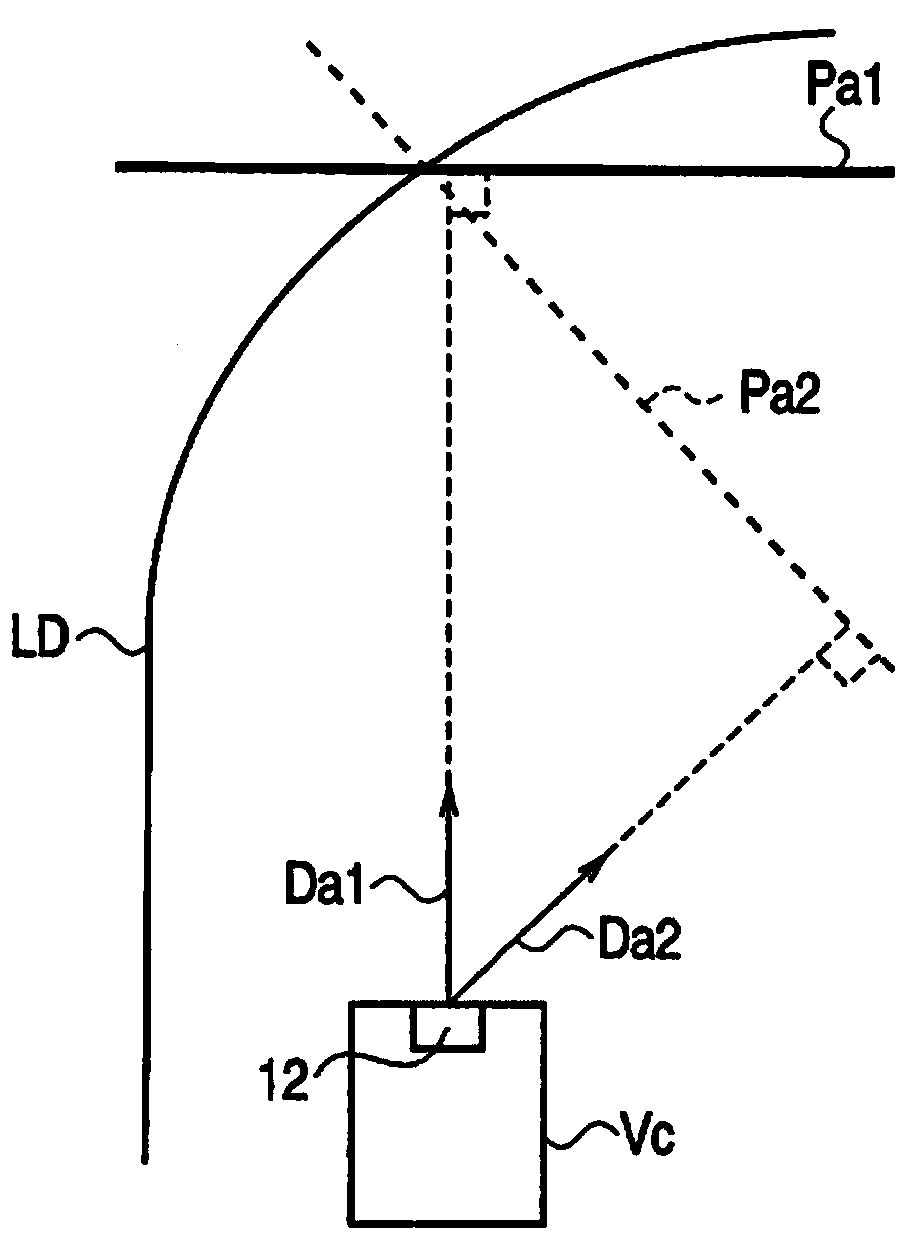
[0090] Sometimes the first step judgment position (Pa 1 ) and the intersection point of the step (LD), and the judgment position of the second step (Pa 2 ) and the intersection of the step (LD) are separated, and it is difficult to properly compare the difference in the slope of the height change of the road surface.
[0091] Therefore, in the third embodiment to the sixth embodiment, for the first step judgment position (Pa 1 ) to estimate the step existence range where the step exists, and set the second step judgment position passing through the step existence range (Pa 2 ) example to illustrate. Specifically, the step detection device (3-6) is also provided with the first step judgment position (Pa 1 ) is a step existence range estimation circuit (21 to 24) for estimating a step existence range in which a step exists. The step judgment position circuit 15 judges the position with the second step (Pa 2 ) to set the second predetermined direction and the second predeter...
PUM
 Abstract
Description
Claims
Application Information