Touch panel and touch display device

A technology of touch display device and touch panel, which is applied in the direction of instrument, electrical digital data processing, input/output process of data processing, etc. It can solve the problem of thermal deformation of ink and achieve the effect of avoiding deformation

Inactive Publication Date: 2016-02-24
INTERFACE OPTOELECTRONICS SHENZHEN +1
View PDF3 Cites 15 Cited by
  • Summary
  • Abstract
  • Description
  • Claims
  • Application Information

AI Technical Summary

Problems solved by technology

[0003] In view of the above, it is necessary to provide a touch panel and a touch display device using the to

Method used


Image

  • Touch panel and touch display device
  • Touch panel and touch display device
  • Touch panel and touch display device

Examples


Example Embodiment

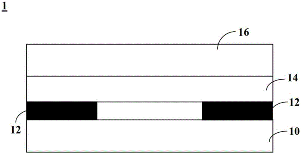
[0032] figure 1 A schematic structural diagram of an existing touch panel 1 is shown. The touch panel 1 includes a protective cover 10 , a first ink layer 12 , an optical adhesive layer 14 and a touch sensing layer 16 . The optical adhesive layer 14 is disposed between the protective cover 10 and the touch sensing layer 16 , and the first ink layer 12 is disposed around the protective cover 10 for shielding the non-sensing area. After bonding the protective cover 10 and the touch sensing layer 16 with the optical adhesive layer 14 , it is necessary to use a curing light source (such as ultraviolet light) to dry and cure the optical adhesive. When the first ink layer is a black or dark ink layer with a high absorption rate, the first ink layer 12 will absorb the heat of the curing light source and deform, resulting in the protective cover 16 and touch The sensing layer 16 is also deformed accordingly.

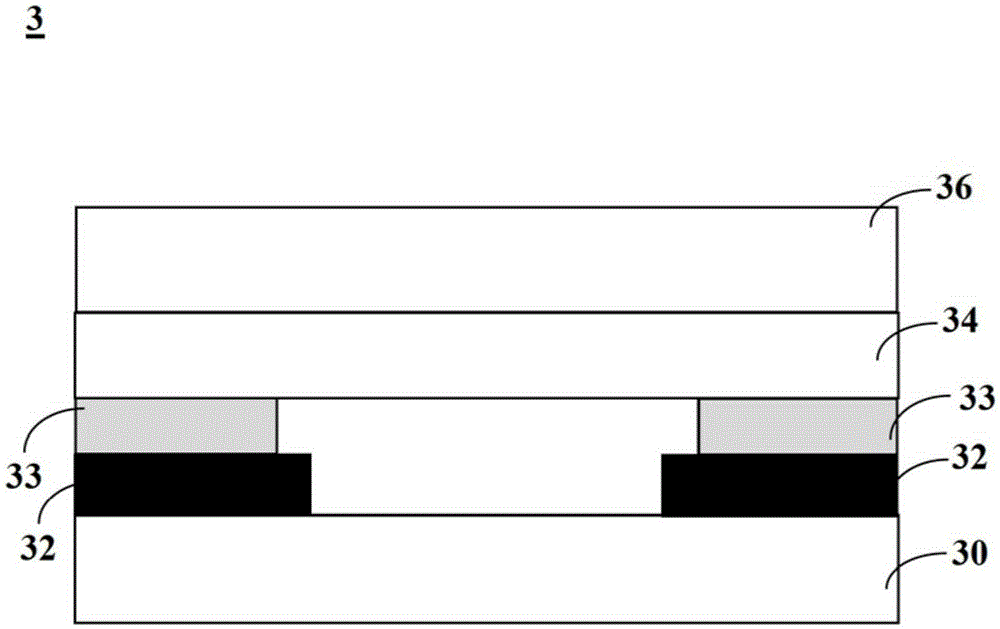
[0033] figure 2 A schematic structural diagram of the touch panel 3 ac...


PUM


Abstract

The invention discloses a touch panel which comprises a protective cover plate, a touch sensing layer and an optical rubber layer. A first ink layer and a second ink layer are arranged between the optical rubber layer and the protective cover plate; the first ink layer is arranged around the protective cover plate; the second ink layer is arranged on the first ink layer; the second in layer has the characteristics of high reflectivity or low absorptivity and low penetration rate. The invention also provides a light source solidifying method of the touch panel, a touch display device comprising the touch panel and a light source solidifying method of the touch display device. The second ink layer with high reflectivity or low absorptivity and low penetration rate is arranged on the first ink layer of the touch panel, so that deformation of the first ink layer caused by heating can be avoided.

Description

technical field [0001] The invention relates to a touch panel and a touch display device. Background technique [0002] The touch panel usually includes a protective cover (glass or plastic material), a touch film (film or glass) and optical glue (Optically Clear Adhesive, OCA), and the optical glue is arranged on the touch film and the protective cover. Between the cover plates, it is used for bonding the touch film and the protective cover plate. The touch panel also includes an ink layer for covering the non-touch area. At present, as the size of the touch module increases, the adhesive force required by the OCA also increases, and the plastic material (CoverLens) is used to replace the glass (CoverGlass) when the protective cover requires lower cost and light weight. When the customer's appearance requirement is black, the OCA light source curing (such as ultraviolet curing, UVcuring) after the LAM process will cause the ink to absorb heat and cause the CoverLens to de...

Claims


Application Information

Patent Timeline
IPC IPC(8): G06F3/041
Inventor 王智勇蔡正丰
Owner INTERFACE OPTOELECTRONICS SHENZHEN
Why Eureka
Try Eureka